
Datasheet

Rt =
(1/F) - 172
*
10
-9
182
*
10
-12
DC =
(0.5 x T
S
) - T
D
T
S
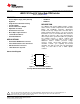
LM5033
www.ti.com
SNVS181B –APRIL 2004–REVISED APRIL 2013
where
• T
S
is the period of each output
• T
D
is the deadtime (1)
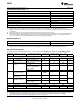
For example, if the oscillator frequency is 200 kHz, each output will cycle at 100 kHz, and T
S
= 10 µs. Using the
nominal deadtime of 135 ns, the maximum duty cycle at this frequency is 48.65%. Using the minimum deadtime
of 85 ns, the maximum duty cycle increases to 49.15%.
When the Softstart pin (pin 10) is pulled down (internally or externally) the Comp pin voltage is pulled down with
it, with a difference of 0.5V. When the Softstart pin voltage increases the Comp voltage is allowed to increase,
pulled up by an internal 5.2V supply through a 5kΩ resistor.
In an open loop application, such as an intermediate bus converter, pin 3 can be left open resulting in maximum
duty cycle at the output drivers .
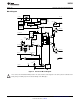
Current Sense (Pin 8)
The current sense circuit is intended to protect the power converter when an abnormal primary current is sensed
by initiating a low duty cycle hiccup mode. When the threshold (0.5V) at Pin 8 is exceeded the outputs are
disabled, and the softstart capacitor (at pin 10) is internally discharged. When the softstart capacitor is fully
discharged and the voltage at the CS pin is below 0.5V, the outputs are re-enabled allowing the softstart
capacitor voltage and the output duty cycle to increase.
The external current sensing circuit should include an RC filter located near the IC to prevent false triggering of
the Current Sense comparator due to transients or noise. An internal MOSFET discharges the external filter
capacitor at the conclusion of each PWM cycle to improve dynamic performance. The discharge time is equal to
the deadtime between Out1 and Out2 at maximum duty cycle. Additionally, pin 8 is pulled low when V
CC
is below
the under-voltage threshold or when an over temperature condition occurs.
Oscillator, Sync Capability (Pin 9)
The LM5033 oscillator frequency is set by a single external resistor connected between Rt/Sync and ground. The
required Rt resistor is calculated from:
(2)
The outputs (Out1 and Out2) alternate at half the oscillator frequency. The voltage at the Rt/Sync pin is internally
regulated to a nominal 2.0V. The Rt resistor should be located as close as possible to the IC, and connected
directly to the pins (Rt and GND).
The LM5033 can be synchronized to an external clock by applying a narrow pulse to pin 9. The external clock
must be a higher frequency than the free running frequency set by the Rt resistor, and the pulse width must be
between 15 and 150 ns. The clock signal must be coupled into the Rt/Sync pin through a 100 pF capacitor.
When the synchronizing pulse transitions low-to-high, the voltage at pin 9 must exceed 3.8V from its nominal
2.0V dc level. During the clock signal’s low time the voltage at pin 9 will be clamped at 2.0V by an internal
regulator. The Rt resistor is always required, whether the oscillator is free running or externally synchronized.
Soft Start (Pin 10)
The softstart feature allows the converter to gradually reach a steady state operating point, thereby reducing
start-up stresses and current surges. Upon turn-on, after the under-voltage sensor resets at V
CC
, an internal 10
µA current source charges an external capacitor at pin 10 to generate a ramping voltage (0 to + 5V) which allows
the voltage on the Comp pin (pin 3) to increase gradually. As the COMP voltage increases the output duty cycle
will increase from zero to the value required for regulation. Internally, the softstart pin is pulled low when a
current fault is detected at pin 8, the V
CC
voltage is below the lower threshold of the under-voltage sensor, or
when a thermal shutdown occurs. Additionally, the softstart pin can be pulled low by an external device.
Copyright © 2004–2013, Texas Instruments Incorporated Submit Documentation Feedback 9
Product Folder Links: LM5033