
Datasheet

ERROR AMP
& ISOLATION
ERROR AMP
& ISOLATION
CS1
CS2
OUT1
OUT2
AC1
AC2
COMP1
COMP2
VIN
SS1
SS2
VCC2
DCL
OVLP
VCC1
RES
UVLO
LM5034
V
CC
3.3V
2.5V
RT
Sync
36V to 75V
Input
GND1 GND2
V
PWR
LM5034
www.ti.com
SNVS347A –FEBRUARY 2005–REVISED APRIL 2013
LM5034 High Voltage Dual Interleaved Current Mode Controller with Active Clamp
Check for Samples: LM5034
1
FEATURES
APPLICATIONS
2
• Two Independent PWM Current Mode
• Telecommunication Power Converters
Controllers
• Industrial Power Converters
• Integrated High Voltage Startup Regulator
• +42V Automotive Systems
• Compound 2.5A Main Output Gate Drivers
DESCRIPTION
• Single Resistor Oscillator Setting to 2 MHz
The LM5034 dual current mode PWM controller
• Synchronizable Oscillator
contains all the features needed to control either two
• Active Clamp Gate Driver for P-Channel
independent forward/active clamp dc/dc converters or
MOSFETs
a single high current converter comprised of two
interleaved power stages. The two controller
• Adjustable Gate Drive Overlap Time
channels operate 180° out of phase thereby reducing
• Programmable Maximum Duty Cycle
input ripple current. The LM5034 includes a startup
• Maximum Duty Cycle Fold-Back at High Line
regulator that operates over a wide input range up to
Voltage
100V and compound (bipolar + CMOS) gate drivers
that provide a robust 2.5A peak sink current. The
• Adjustable Timer for Hiccup Mode Current
adjustable dead-time of the active clamp gate drivers
Limiting
and adjustable maximum PWM duty cycle reduce
• Integrated Slope Compensation
stress on the primary side MOSFET switches.
• Adjustable Line Under-Voltage Lockout
Additional features include programmable line under-
voltage lockout, cycle-by-cycle current limit, hiccup
• Independently Adjustable Soft-Start (Each
mode fault operation with adjustable restart delay,
Regulator)
PWM slope compensation, soft-start, and a 2 MHz
• Direct Interface with Opto-Coupler Transistor
capable oscillator with synchronization capability.
• Thermal Shutdown
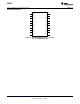
PACKAGE
• TSSOP-20
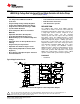
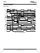
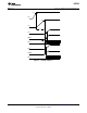
Typical Application Circuit
Figure 1. Dual Interleaved Regulators with Independent Outputs
1
Please be aware that an important notice concerning availability, standard warranty, and use in critical applications of
Texas Instruments semiconductor products and disclaimers thereto appears at the end of this data sheet.
2All trademarks are the property of their respective owners.
PRODUCTION DATA information is current as of publication date.
Copyright © 2005–2013, Texas Instruments Incorporated
Products conform to specifications per the terms of the Texas
Instruments standard warranty. Production processing does not
necessarily include testing of all parameters.