LM5039 Application Note 2025 LM5039 Evaluation Board Literature Number: SNVA423C
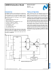
National Semiconductor Application Note 2025 Ajay Hari February 17, 2010 Introduction Theory of Operation The LM5039 evaluation board is designed to provide the design engineer with a fully functional power converter based on the half-bridge topology to evaluate the LM5039 controller. The evaluation board is provided in an industry standard quarter brick footprint. The performance of the evaluation board is as follows: • Input Operating Range: 36V to 75V • Output Voltage: 3.
AN-2025 The secondary side employs synchronous rectification scheme, which is controlled by the LM5039, during the softstart, the sync FET body diodes act as the secondary rectifiers. Once, the soft-start is finished, the synchronous rectifiers are engaged with a non-overlap time programmed by the DLY resistor. Feedback from the output is processed by an amplifier and reference, generating an error voltage, which is coupled back to the primary side control through an opto-coupler.
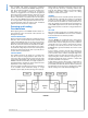
Average Current Limit The major drawback of the half-bridge topology is that during current limit condition, the center-point of the capacitor divider tends to runaway either towards the input voltage rail or towards the ground. This phenomenon saturates the transformer and requires the capacitors in the divider to be rated to at least the input voltage. In an overload condition, the PWM cycle is terminated by the current sense comparator instead of the PWM comparator.
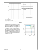
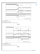
AN-2025 30112704 Trace 1 (C1) Output Voltage Trace 2(C2): Voltage on the ACL Capacitor Trace 3 (C4): Voltage at the center-point of the half-bridge capacitor divider FIGURE 3. The LM5039 evaluation board is configured to be in constant current limiting. To configure the board for hiccup mode restart, remove the zero ohm resistor from the RES pin to the AGND and install a 4700pF capacitor from the RES pin to the AGND.
AN-2025 30112706 Trace 1 (C1): Output voltage Trace 2(C2): Voltage on the ACL capacitor Trace 3(C3): Voltage on the RES capacitor Trace 4(C4): Voltage at the center-point of the half-bridge capacitor divider FIGURE 5. 30112707 Trace 1 (C1): Output voltage Trace 2(C2): Voltage on the ACL capacitor Trace 3(C3): Voltage on the RES capacitor Trace 4(C4): Voltage at the center-point of the half-bridge capacitor divider FIGURE 6. 5 www.national.
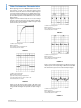
AN-2025 Other Performance Characteristics When applying power to the LM5039 evaluation board a certain sequence of events occurs. Soft-start capacitor values and other components allow for a minimal output voltage for a short time until the feedback loop can stabilize without overshoot. Figure 7 shows the output voltage during a typical startup with a 48V input and a load of 30A. There is no overshoot during start-up. Figure 8 shows the transient response for a load of change from 5A to 25A.
FIGURE 12. 30112711 AN-2025 7 www.national.
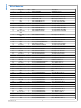
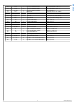
AN-2025 Bill of Materials # Designator Qty Part # Description 1 U1 2 U2 1 NSC LM5039MH LM5039 Controller 1 NSC LM5110-1M 3 LM5110-1M Dual Driver U3 1 NSC LM8261M5 4 LM8261M5 Op Amp U5 1 NSC LM4041AIM3-.12 LM4041AIM3-1.
R16 1 Vishay CRCW08056492F Res 64.9K OHM 1/10W 1% 49 R10 2 Vishay CRCW08051003F Res 100K OHM 1/10W 1% 50 R8, R9 2 Vishay CRCW201010R0F Res 10 OHM 1% 51 D1 1 BAV70-TP Schottky, Diode, 75V 150mA 52 D2, D4 2 Central CMDD4448 Diode, 75V 250mA 53 D3 1 BAT54A Schottky Diode, 30V 200mA 54 BR1 1 BAT54BRW Diodes, Rectifier, Bridge, 30V 55 Z1 1 Central CMPZ4694 Zener 8.
AN-2025 PCB Layouts 30112713 Top Silk 30112714 Bottom Silk www.national.
AN-2025 30112715 Top Side 30112716 Layer 2 11 www.national.
AN-2025 30112717 Layer 3 30112718 Layer 4 www.national.
AN-2025 30112719 Layer 5 30112720 Bottom 13 www.national.
LM5039 Evaluation Board Notes For more National Semiconductor product information and proven design tools, visit the following Web sites at: www.national.com Products Design Support Amplifiers www.national.com/amplifiers WEBENCH® Tools www.national.com/webench Audio www.national.com/audio App Notes www.national.com/appnotes Clock and Timing www.national.com/timing Reference Designs www.national.com/refdesigns Data Converters www.national.com/adc Samples www.national.
IMPORTANT NOTICE Texas Instruments Incorporated and its subsidiaries (TI) reserve the right to make corrections, modifications, enhancements, improvements, and other changes to its products and services at any time and to discontinue any product or service without notice. Customers should obtain the latest relevant information before placing orders and should verify that such information is current and complete.