
Datasheet

LM5113
www.ti.com
SNVS725F –JUNE 2011–REVISED APRIL 2013
LM5113 5A, 100V Half-Bridge Gate Driver for Enhancement Mode GaN FETs
Check for Samples: LM5113
1
FEATURES
DESCRIPTION
2
• Independent High-Side and Low-Side TTL
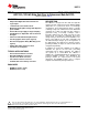
The LM5113 is designed to drive both the high-side
Logic Inputs
and the low-side enhancement mode Gallium Nitride
• 1.2A/5A Peak Source/Sink Current
(GaN) FETs in a synchronous buck or a half bridge
• High-Side Floating Bias Voltage Rail Operates
configuration. The floating high-side driver is capable
up to 100VDC
of driving a high-side enhancement mode GaN FET
operating up to 100V. The high-side bias voltage is
• Internal Bootstrap Supply Voltage Clamping
generated using a bootstrap technique and is
• Split Outputs for Adjustable Turn-on/Turn-off
internally clamped at 5.2V, which prevents the gate
Strength
voltage from exceeding the maximum gate-source
• 0.6Ω /2.1Ω Pull-down/Pull-up Resistance
voltage rating of enhancement mode GaN FETs. The
inputs of the LM5113 are TTL logic compatible, and
• Fast Propagation Times (28ns Typical)
can withstand input voltages up to 14V regardless of
• Excellent Propagation Delay Matching (1.5ns
the VDD voltage. The LM5113 has split gate outputs,
Typical)
providing flexibility to adjust the turn-on and turn-off
• Supply Rail Under-Voltage Lockout strength independently.
• Low Power Consumption
In addition, the strong sink capability of the LM5113
maintains the gate in the low state, preventing
TYPICAL APPLICATIONS
unintended turn-on during switching. The LM5113
can operate up to several MHz. The LM5113 is
• Current Fed Push-Pull converters
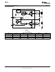
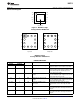
available in a standard WSON-10 pin package and a
• Half and Full-Bridge converters
12-bump DSBGA package. The WSON-10 pin
package contains an exposed pad to aid power
• Synchronous Buck converters
dissipation. The DSBGA package offers a compact
• Two-switch Forward converters
footprint and minimized package inductance.
• Forward with Active Clamp converters
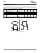
PACKAGES
• WSON-10 (4 mm x 4 mm)
• DSBGA (2 mm x 2 mm)
1
Please be aware that an important notice concerning availability, standard warranty, and use in critical applications of
Texas Instruments semiconductor products and disclaimers thereto appears at the end of this data sheet.
2All trademarks are the property of their respective owners.
PRODUCTION DATA information is current as of publication date.
Copyright © 2011–2013, Texas Instruments Incorporated
Products conform to specifications per the terms of the Texas
Instruments standard warranty. Production processing does not
necessarily include testing of all parameters.