
Datasheet

LM5118, LM5118-Q1
www.ti.com
SNVS566G –APRIL 2008–REVISED FEBRUARY 2013
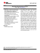
Wide Voltage Range Buck-Boost Controller
Check for Samples: LM5118, LM5118-Q1
1
FEATURES
DESCRIPTION
The LM5118 wide voltage range Buck-Boost
2
• LM5118-Q1 is an Automotive Grade product
switching regulator controller features all of the
that is AEC-Q100 grade 1 qualified (-40°C to
functions necessary to implement a high
125°C operating junction temperature)
performance, cost efficient Buck-Boost regulator
• Ultra-wide input voltage range from 3V to 75V
using a minimum of external components. The Buck-
Boost topology maintains output voltage regulation
• Emulated peak current mode control
when the input voltage is either less than or greater
• Smooth transition between step-down and
than the output voltage making it especially suitable
step- up modes
for automotive applications. The LM5118 operates as
• Switching frequency programmable to 500KHz
a buck regulator while the input voltage is sufficiently
greater than the regulated output voltage and
• Oscillator synchronization capability
gradually transitions to the buck-boost mode as the
• Internal high voltage bias regulator
input voltage approaches the output. This dual mode
• Integrated high and low-side gate drivers
approach maintains regulation over a wide range of
• Programmable soft-start time input voltages with optimal conversion efficiency in
the buck mode and a glitch-free output during mode
• Ultra low shutdown current
transitions. This easy to use controller includes
• Enable input wide bandwidth error amplifier
drivers for the high side buck MOSFET and the low
• 1.5% feedback reference accuracy
side boost MOSFET. The regulators control method
is based upon current mode control utilizing an
• Thermal shutdown
emulated current ramp. Emulated current mode
control reduces noise sensitivity of the pulse-width
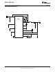
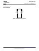
PACKAGE
modulation circuit, allowing reliable control of the very
• HTSSOP-20 (Exposed pad)
small duty cycles necessary in high input voltage
applications. Additional protection features include
current limit, thermal shutdown and an enable input.
The device is available in a power enhanced
HTSSOP-20 package featuring an exposed die attach
pad to aid thermal dissipation.
1
Please be aware that an important notice concerning availability, standard warranty, and use in critical applications of
Texas Instruments semiconductor products and disclaimers thereto appears at the end of this data sheet.
2All trademarks are the property of their respective owners.
PRODUCTION DATA information is current as of publication date.
Copyright © 2008–2013, Texas Instruments Incorporated
Products conform to specifications per the terms of the Texas
Instruments standard warranty. Production processing does not
necessarily include testing of all parameters.