
Datasheet
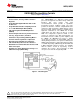

LM628, LM629
www.ti.com
SNVS781C –JUNE 1999–REVISED MARCH 2013
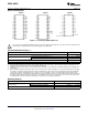
DC Electrical Characteristics
(V
DD
and T
A
per Operating Ratings; f
CLK
= 6 MHz)
Tested Limits
Symbol Parameter Conditions Units
Min Max
I
DD
Supply Current Outputs Open 110 mA
INPUT VOLTAGES
V
IH
Logic 1 Input Voltage 2.0 V
V
IL
Logic 0 Input Voltage 0.8 V
I
IN
Input Currents 0 ≤ V
IN
≤ V
DD
−10 10 μA
OUTPUT VOLTAGES
V
OH
Logic 1 I
OH
= −1.6 mA 2.4 V
V
OL
Logic 0 I
OL
= 1.6 mA 0.4 V
I
OUT
TRI-STATE Output Leakage Current 0 ≤ V
OUT
≤ V
DD
−10 10 μA
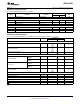
AC Electrical Characteristics
(V
DD
and T
A
per Operating Ratings; f
CLK
= 6 MHz; C
LOAD
= 50 pF; Input Test Signal t
r
= t
f
= 10 ns)
Tested Limits
Timing Interval T# Units
Min Max
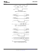
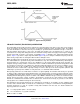
ENCODER AND INDEX TIMING (See Figure 3)
Motor-Phase Pulse Width T1
μs
T2
Dwell-Time per State μs
Index Pulse Setup and Hold
T3 0 μs
(Relative to A and B Low)
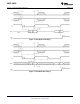
CLOCK AND RESET TIMING (See Figure 4)
LM628N-6, LM629N-6, T4 78 ns
LM629M-6
Clock Pulse Width
LM628N-8, LM629N-8, T4 57 ns
LM629M-8
LM628N-6, LM629N-6, T5 166 ns
LM629M-6
Clock Period
LM628N-8, LM629N-8, T5 125 ns
LM629M-8
T6
Reset Pulse Width μs
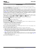
STATUS BYTE READ TIMING (See Figure 5)
Chip-Select Setup/Hold Time T7 0 ns
Port-Select Setup Time T8 30 ns
Port-Select Hold Time T9 30 ns
Read Data Access Time T10 180 ns
Read Data Hold Time T11 0 ns
RD High to Hi-Z Time T12 180 ns
Copyright © 1999–2013, Texas Instruments Incorporated Submit Documentation Feedback 3
Product Folder Links: LM628 LM629