
Datasheet

LM628, LM629
www.ti.com
SNVS781C –JUNE 1999–REVISED MARCH 2013
THEORY OF OPERATION
INTRODUCTION
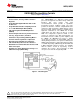
The typical system block diagram (See Figure 1) illustrates a servo system built using the LM628. The host
processor communicates with the LM628 through an I/O port to facilitate programming a trapezoidal velocity
profile and a digital compensation filter. The DAC output interfaces to an external digital-to-analog converter to
produce the signal that is power amplified and applied to the motor. An incremental encoder provides feedback
for closing the position servo loop. The trapezoidal velocity profile generator calculates the required trajectory for
either position or velocity mode of operation. In operation, the LM628 subtracts the actual position (feedback
position) from the desired position (profile generator position), and the resulting position error is processed by the
digital filter to drive the motor to the desired position. Table 1 provides a brief summary of specifications offered
by the LM628/LM629:
POSITION FEEDBACK INTERFACE
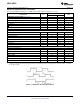
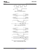
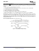
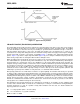
The LM628 interfaces to a motor via an incremental encoder. Three inputs are provided: two quadrature signal
inputs, and an index pulse input. The quadrature signals are used to keep track of the absolute position of the
motor. Each time a logic transition occurs at one of the quadrature inputs, the LM628 internal position register is
incremented or decremented accordingly. This provides four times the resolution over the number of lines
provided by the encoder. See Figure 10. Each of the encoder signal inputs is synchronized with the LM628 clock.
The optional index pulse output provided by some encoders assumes the logic-low state once per revolution. If
the LM628 is so programmed by the user, it will record the absolute motor position in a dedicated register (the
index register) at the time when all three encoder inputs are logic low.
If the encoder does not provide an index output, the LM628 index input can also be used to record the home
position of the motor. In this case, typically, the motor will close a switch which is arranged to cause a logic-low
level at the index input, and the LM628 will record motor position in the index register and alert (interrupt) the
host processor. Permanently grounding the index input will cause the LM628 to malfunction.
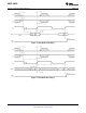
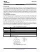
Table 1. System Specifications Summary
Position Range −1,073,741,824 to 1,073,741,823 counts
Velocity Range 0 to 1,073,741,823/2
16
counts/sample; ie, 0 to 16,383 counts/sample, with a resolution of 1/2
16
counts/sample
Acceleration Range 0 to 1,073,741,823/2
16
counts/sample/sample; ie, 0 to 16,383 counts/sample/sample, with a resolution of 1/2
16
counts/sample/sample
Motor Drive Output LM628: 8-bit parallel output to DAC, or 12-bit multiplexed output to DAC
LM629: 8-bit PWM sign/magnitude signals
Operating Modes Position and Velocity
Feedback Device Incremental Encoder (quadrature signals; support for index pulse)
Control Algorithm Proportional Integral Derivative (PID) (plus programmable integration limit)
Sample Intervals Derivative Term: Programmable from 2048/f
CLK
to (2048 * 256)/f
CLK
in steps of 2048/f
CLK
(256 to 65,536 μs for
an 8.0 MHz clock).
Proportional and Integral: 2048/f
CLK
Figure 10. Quadrature Encoder Signals
Copyright © 1999–2013, Texas Instruments Incorporated Submit Documentation Feedback 9
Product Folder Links: LM628 LM629