
Datasheet


LM79L05AC is OBSOLETE
LM79L05, LM79L12, LM79L12AC
LM79L15, LM79L15AC
www.ti.com
SNOSBR8K –JULY 1999–REVISED APRIL 2013
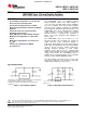
LM79LXXAC Series 3-Terminal Negative Regulators
Check for Samples: LM79L05, LM79L12, LM79L12AC, LM79L15, LM79L15AC
1
FEATURES
DESCRIPTION
The LM79LXXAC series of 3-terminal negative
2
• Preset Output Voltage Error is Less than ±5%
voltage regulators features fixed output voltages of
Over Load, Line and Temperature
−5V, −12V, and −15V with output current capabilities
• Specified at an Output Current of 100mA
in excess of 100mA. These devices were designed
• Easily Compensated with a Small 0.1μF Output
using the latest computer techniques for optimizing
the packaged IC thermal/electrical performance. The
Capacitor
LM79LXXAC series, when combined with a minimum
• Internal Short-Circuit, Thermal and Safe
output capacitor of 0.1μF, exhibits an excellent
Operating Area Protection
transient response, a maximum line regulation of
• Easily Adjustable to Higher Output Voltages
0.07% V
O
/V, and a maximum load regulation of
0.01% V
O
/mA.
• Maximum Line Regulation Less than 0.07%
V
OUT
/V
The LM79LXXAC series also includes, as self-
• Maximum Load Regulation Less than 0.01%
protection circuitry: safe operating area circuitry for
output transistor power dissipation limiting, a
V
OUT
/mA
temperature independent short circuit current limit for
• See AN-1112 (SNVA009) for DSBGA
peak output current limiting, and a thermal shutdown
Considerations
circuit to prevent excessive junction temperature.
Although designed primarily as fixed voltage
regulators, these devices may be combined with
simple external circuitry for boosted and/or adjustable
voltages and currents. The LM79LXXAC series is
available in the 3-lead TO package, the 8-lead SOIC
package, and the 6-Bump DSBGA package.
For output voltages other than the pre-set -5V, -12V
and -15V, the LM137L series provides an adjustable
output voltage range from -1.2V to -47V.
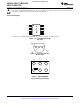
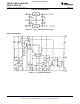
Typical Applications
*Required if the regulator is located far from the power supply filter.
A 1μF aluminum electrolytic may be substituted.
−V
0
= −5V − (5V/R1 + I
Q
) • R2,
**Required for stability. A 1μF aluminum electrolytic may be
5V/R1 > 3 I
Q
substituted.
Figure 1. Fixed Output Regulator Figure 2. Adjustable Output Regulator
1
Please be aware that an important notice concerning availability, standard warranty, and use in critical applications of
Texas Instruments semiconductor products and disclaimers thereto appears at the end of this data sheet.
2All trademarks are the property of their respective owners.
PRODUCTION DATA information is current as of publication date.
Copyright © 1999–2013, Texas Instruments Incorporated
Products conform to specifications per the terms of the Texas
Instruments standard warranty. Production processing does not
necessarily include testing of all parameters.