LM86, LM89, LM89-1, LM90, LM99, LM99-1 Evaluation Board User’s Guide Copyright 2003 National Semiconductor Corporation 1
Table of Contents 1.0 Introduction . . . . . . . . . . . . . . . . . . . . . . . . . . . . . . . . . . . . . . . . . . . . . . 3, 4 2.0 Getting Started . . . . . . . . . . . . . . . . . . . . . . . . . . . . . . . . . . . . . . . . . . . . . 4 2.1 2.2 2.3 2.4 2.5 Required Equipment . . . . . . . . . . . . . . . . . . . . . . . . . . . . . . . . . . . . 4 Optional Equipment . . . . . . . . . . . . . . . . . . . . . . . . . . . . . . . . . . . . . 4 Test Setup – Software . . . . . . . . . . . . . . . . . .
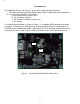
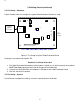
1.0 Introduction The LMxxEVAL kit (xx = 86, 89, 89-1, 90, 99, 99-1) includes the following items: 1. The LMxx Evaluation Board (for LM86, LM89, LM89-1, LM90, LM99, LM99-1 products) 2. The SensorEval Software CD, including a. the readme.txt file (read this first) b. the installation setup file, c. the SensorEval Software manual, and d. this manual. The LMxx Evaluation Board, as shown in Figure 1, is a complete PCBA (printed circuit board assembly).
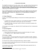
1.0 Introduction (Continued) The LMxxEVAL kit includes the SensorEval software, which is provided by National Semiconductor to communicate with the LMxx Evaluation Board by way of the USB cable (not provided) from the controlling computer. The SensorEval software is used to control the writing and reading of the digital registers in the LMxx for doing the initial register setup, reading the local and remote temperatures, establishing certain temperature limit setpoints.
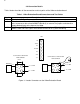
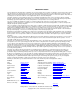
2.0 Getting Started (continued) 2.4 Test Setup – Hardware Figure 2 below shows an example of a typical LMxx Evaluation Board test setup. J4 Computer USB Port Connection Q1 J3 U3 JP2 LMxx NC 7 TCRIT# 6 NC 5 ALERT# 4 SCL 3 SDA 2 +3.3 1 No jumpers required National Semiconductor LM86 Evaluation Board Rev. 2 LMxx = LM86, LM89, LM89-1, LM90, LM99, or LM99-1 Figure 2. Test Setup using the LMxx Evaluation Board No jumpers are required on header JP2. Hardware Test Setup Procedure 1.
3.0 Connection Details Table 1 below describes all the connections and test points of the LMxx evaluation board. Table 1. LMxx Evaluation Board Connections and Test Points Description of the Connections Symbol J3 This is the USB Type B connector to connect to the computer. J4 This allows the user to either: (1) connect jumpers horizontally to the top and bottom pin pairs to connect to the on-board MMBT3904 or (2) to remove the jumpers and connect a remote diode directly to the input of the LMxx.
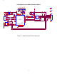
4.0 Schematic of the LMxx Evaluation Board + 3.3 VDC C1 0.1uF D+ GND SHELL_1 SHELL_2 2 24 R9 22 3 4 5 6 25 R11 1.5K + 3.3 VDC R12 1M A0 Vcc A1 WP A2 SCL Vss SDA 18 8 7 R13 1.5K R14 1.5K 10 11 12 USBD- SCL 2 5 SDA 3 7 6 XIN PB6/INT6 PB7/T2OUT CTL2/AOUTFLAG CTL0/AINFLAG PC0/RxD0 PC1/TxD0 U2 DISCON# CY7C64603-52NC PA4/FWR# PA5/FRD# CLKOUT C20 0.1uF 6 20 29 30 31 32 33 34 USBD+ SCL SDA C11 C12 2.2uF 0.1uF C13 R2 1.5K 100 pF R15 1.
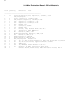
5.0 LMxx Evaluation Board - Bill of Materials Item Quantity Reference Part ______________________________________________ 1 11 2 3 4 5 6 7 8 9 10 11 12 13 14 15 16 17 18 19 20 33 34 2 3 1 1 1 1 1 1 1 1 5 1 2 2 4 1 1 1 1 1 1 C1,C2,C3,C4,C5,C6,C12, Capacitor, ceramic,0.1uF C15,C17,C18,C20 C9,C10 Capacitor, ceramic,33pF C11,C14,C16 Capacitor, ceramic,2.2uF C13 Capacitor, ceramic,100 pF C19 Capacitor, ceramic,2.
IMPORTANT NOTICE Texas Instruments Incorporated and its subsidiaries (TI) reserve the right to make corrections, modifications, enhancements, improvements, and other changes to its products and services at any time and to discontinue any product or service without notice. Customers should obtain the latest relevant information before placing orders and should verify that such information is current and complete.