
Datasheet

LMC6442
www.ti.com
SNOS013E –SEPTEMBER 1997–REVISED MARCH 2013
LMC6442 Dual Micropower Rail-to-Rail Output Single Supply Operational Amplifier
Check for Samples: LMC6442
1
FEATURES
DESCRIPTION
The LMC6442 is ideal for battery powered systems,
2
• (Typical, V
S
= 2.2V)
where very low supply current (less than one
• Output Swing to Within 30 mV of Supply Rail
microamp per amplifier) and Rail-to-Rail output swing
• High Voltage Gain 103 dB
is required. It is characterized for 2.2V to 10V
operation, and at 2.2V supply, the LMC6442 is ideal
• Gain Bandwidth Product 9.5 KHz
for single (Li-Ion) or two cell (NiCad or alkaline)
• Ensured for: 2.2V, 5V, 10V
battery systems.
• Low Supply Current 0.95 µA/Amplifier
The LMC6442 is designed for battery powered
• Input Voltage Range −0.3V to V
+
-0.9V
systems that require long service life through low
• 2.1 µW/Amplifier Power Consumption
supply current, such as smoke and gas detectors,
and pager or personal communications systems.
• Stable for A
V
≥ +2 or A
V
≤ −1
Operation from single supply is enhanced by the wide
APPLICATIONS
common mode input voltage range which includes the
ground (or negative supply) for ground sensing
• Portable Instruments
applications. Very low (5 fA, typical) input bias current
• Smoke/Gas/CO/Fire Detectors
and near constant supply current over supply voltage
• Pagers/Cell Phones
enhance the LMC6442's performance near the end-
of-life battery voltage.
• Instrumentation
• Thermostats
Designed for closed loop gains of greater than plus
two (or minus one), the amplifier has typically 9.5
• Occupancy Sensors
KHz GBWP (Gain Bandwidth Product). Unity gain can
• Cameras
be used with a simple compensation circuit, which
• Active Badges
also allows capacitive loads of up to 300 pF to be
driven, as described in the Application Information
section.
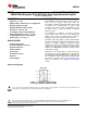
Connection Diagram
Top View
Figure 1. 8-Pin SOIC / PDIP Package
See Package Numbers D0008A, P0008E
These devices have limited built-in ESD protection. The leads should be shorted together or the device placed in conductive foam
during storage or handling to prevent electrostatic damage to the MOS gates.
1
Please be aware that an important notice concerning availability, standard warranty, and use in critical applications of
Texas Instruments semiconductor products and disclaimers thereto appears at the end of this data sheet.
2All trademarks are the property of their respective owners.
PRODUCTION DATA information is current as of publication date.
Copyright © 1997–2013, Texas Instruments Incorporated
Products conform to specifications per the terms of the Texas
Instruments standard warranty. Production processing does not
necessarily include testing of all parameters.