
Datasheet

LMH1982 Evaluation Board
USB Board
USB
Node
PC
COP8
USB Current
Sense
USB
Cable
USB 5V
LDOs
LMH1981
LMH1982
I
2
C
Ref. In
PC
USB
SD_CLK
HD_CLK
I/O
signals
Ext.
H/V In
3.3V and 2.5V
LPF+VCXO
User's Guide
SNOA527A–May 2008–Revised April 2013
AN-1841 LMH1982 Evaluation Board
1 Introduction
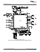
The LMH1982 evaluation board was designed by Texas Instruments to evaluate the performance and
operation of the LMH1982 multi-rate video clock and timing generator with the LMH1981 SD/HD video
sync separator. The evaluation board provides input ports to receive analog or digital reference signals,
SMA connector ports to transmit the differential output clocks, and headers to access various input/output
signals. On-board toggle switches allow control over the sync inputs and control inputs, such as device
reset. A USB interface board is also provided to allow programming of the LMH1982 through a PC's USB
port using TI's LMH1982 evaluation software.
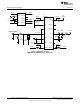
Refer to the Evaluation Board Schematic, PCB Layout, and Bill of Materials sections, as well as the
collateral listed in the References section.
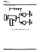
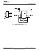
1.1 USB Interface Board
Headers X2 and X4 of the USB interface board should be plugged into headers J7 and J11 of the
evaluation board. The USB board's firmware supports the I
2
C interface, which enables the user to program
the LMH1982 from a PC running the evaluation software. The USB board can also provide 5V from the
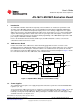
PC's USB port to power the LDO regulators on the evaluation board. The block diagram in Figure 1 shows
the connections between the PC, USB board, and evaluation board.
Figure 1. Simplified Block Diagram of the Evaluation Setup
1.2 Power Supplies
The evaluation board requires a 5V supply and ground connection to power the on-board LP38693 LDO
regulators (U1, U2).
To use 5V from the USB port via header J7, shunt pins 1 and 2 of jumper JP3. Refer to Table 1 for the pin
assignment of JP3. If the USB supply is used, make sure that the USB port of the PC is capable of
nominally sourcing 150 mA (0.75W at 5V). When powering the evaluation board, the USB supply voltage
should measure 5V ± 5% at pin 4 of J7.
All trademarks are the property of their respective owners.
1
SNOA527A–May 2008–Revised April 2013 AN-1841 LMH1982 Evaluation Board
Submit Documentation Feedback
Copyright © 2008–2013, Texas Instruments Incorporated