
Datasheet


www.ti.com
Evaluation Board Layout
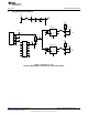
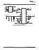
3 Evaluation Board Layout
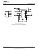
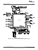
Figure 7. PCB Layout (1 of 2)
Top Routing Layer 1 (dark gray) and Ground Plane Layer 2 (light gray)
11
SNOA527A–May 2008–Revised April 2013 AN-1841 LMH1982 Evaluation Board
Submit Documentation Feedback
Copyright © 2008–2013, Texas Instruments Incorporated