
Datasheet

Introduction
www.ti.com
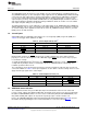
Table 8. Genlock Status LEDs
Condition D3 D4
(NO_LOCK) (NO_REF)
Genlock mode OFF OFF
Reference lost
PLL(s) not locked
Genlock mode OFF ON
Reference valid
PLL(s) locking
Genlock mode ON ON
Reference valid
PLLs locked
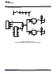
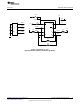
1.10 I
2
C Interface
The I
2
C interface clock (SCL) and data (SDA) signals come from the USB board via header J11. These
signals can be probed at test points TP11 (SCL) and TP12 (SDA). Both signals traces have 4.7 kΩ pull-up
resistors to VDD and 50Ω series resistors to the I
2
C pins of the LMH1982. The I2C_ENABLE input must
be set high to allow I
2
C programming.
1.11 USB Board and PC Software Application
When connected to the PC the Windows operating system (OS) will interpret the USB board as a Human
Interface Device (HID) and use Microsoft’s standard HID driver included in the OS. The LMH1982
evaluation software application can access the USB board through dynamic link libraries, which are used
by the PC application to control the LMH1982 using the I
2
C interface. For more information, consult the
USB board reference manual and LMH1982 evaluation software user guide.
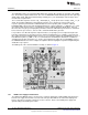
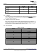
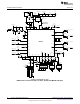
1.12 List of Test Points
Table 9. Test Points
Designator Signal Name
TP1 DVDD
TP2 VCC
TP3 VDD
TP4 VDD_VCXO
TP7 OEOUT
TP11 SCL
TP12 SDA
Pin 6, J10 TOF_OUT
Pin 7, J10 NO_LOCK
Pin 8, J10 NO_REF
TP21 VCTRL
TP22 XO_OUT
TP23 TOF
TP27 HREF_A
TP28 VREF_A
TP30 HREF_B
TP31 VREF_B
6
AN-1841 LMH1982 Evaluation Board SNOA527A–May 2008–Revised April 2013
Submit Documentation Feedback
Copyright © 2008–2013, Texas Instruments Incorporated