
Datasheet
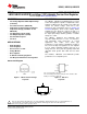


REF CATHODE
ANODE
LMV431, LMV431A, LMV431B
www.ti.com
SNVS041F –MAY 2004–REVISED MAY 2005
LMV431/LMV431A/LMV431B Low-Voltage (1.24V) Adjustable Precision Shunt Regulators
Check for Samples: LMV431, LMV431A, LMV431B
1
FEATURES
DESCRIPTION
The LMV431, LMV431A and LMV431B are precision
2
• Low Voltage Operation/Wide Adjust Range
1.24V shunt regulators capable of adjustment to 30V.
(1.24V/30V)
Negative feedback from the cathode to the adjust pin
• 0.5% Initial Tolerance (LMV431B)
controls the cathode voltage, much like a non-
• Temperature Compensated for Industrial
inverting op amp configuration (Refer to Symbol and
Functional diagrams). A two resistor voltage divider
Temperature Range (39 PPM/°C for the
terminated at the adjust pin controls the gain of a
LMV431AI)
1.24V band-gap reference. Shorting the cathode to
• Low Operation Current (55µA)
the adjust pin (voltage follower) provides a cathode
• Low Output Impedance (0.25Ω)
voltage of a 1.24V.
• Fast Turn-On Response
The LMV431, LMV431A and LMV431B have
• Low Cost
respective initial tolerances of 1.5%, 1% and 0.5%,
and functionally lends themselves to several
applications that require zener diode type
APPLICATIONS
performance at low voltages. Applications include a
• Shunt Regulator
3V to 2.7V low drop-out regulator, an error amplifier
• Series Regulator
in a 3V off-line switching regulator and even as a
voltage detector. These parts are typically stable with
• Current Source or Sink
capacitive loads greater than 10nF and less than
• Voltage Monitor
50pF.
• Error Amplifier
The LMV431, LMV431A and LMV431B provide
• 3V Off-Line Switching Regulator
performance at a competitive price.
• Low Dropout N-Channel Series Regulator
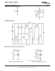
Connection Diagram
*Pin 1 is not internally connected.
*Pin 2 is internally connected to Anode pin. Pin 2 should be either
floating or connected to Anode pin.
Figure 1. TO-92: Plastic Package Figure 2. SOT-23-5
Top View Top View
Figure 3. SOT-23-3
Top View
1
Please be aware that an important notice concerning availability, standard warranty, and use in critical applications of
Texas Instruments semiconductor products and disclaimers thereto appears at the end of this data sheet.
2All trademarks are the property of their respective owners.
PRODUCTION DATA information is current as of publication date.
Copyright © 2004–2005, Texas Instruments Incorporated
Products conform to specifications per the terms of the Texas
Instruments standard warranty. Production processing does not
necessarily include testing of all parameters.