
Datasheet

P
3
Out
+
-
R
2
100:
P
2
RFin
C
2
22 pF
C
4
10 µF
C
3
100 pF
P
1
V
DD
P
4
V
SS
+
C
1
100 pF
C
5
10 µF
+
R
1
100:
P
5
GND
U
1
LMV831
1
3
2
4
5
www.ti.com
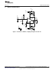
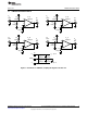
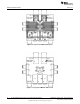
LMV831 Evaluation Board
9 LMV831 Evaluation Board
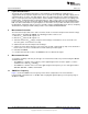
Figure 3. Schematic for LMV831, Coupling RF Signal to the IN+ Pin
5
SNOA530A–October 2008–Revised April 2013 AN-1867 EMIRR Evaluation Boards for LMV831/LMV832/LMV834
Submit Documentation Feedback
Copyright © 2008–2013, Texas Instruments Incorporated