
Datasheet
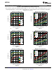
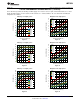


PGND/EP
Connect to AGND
5
AGND
6
AGND
3
AGND
1
VIN
2
VIN
4
EN
7
FB
SS
9
NC
10
VOUT
11
VOUT
8
V
IN
C
IN
3 x 10 PF
R
FBT
C
FF
4.7 nF (OPT)
See Table
C
SS
0.47 PF
(OPT)
R
FBB
See Table
C
OUT
2 x 330 PF
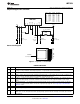
LMZ13608
VOUT
SS
FB
VIN
EN
PGND
V
OUT
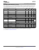
5V 5.62k 1.07k 7...36V
V
OUT
R
FBT
R
FBB
V
IN
Range
3.3V 3.32k 1.07k 6...36V
2.5V 2.26k 1.07k 6...36V
1.8V 1.87k 1.50k 6...36V
1.5V 1.00k 1.13k 6...36V
1.2V 1.07k 2.05k 6...36V
0.8V 0 4.02k 6...36V
AGND
6V 15.4k 2.37k 8.5...36V
1.0V 1.62k 6.49k 6...36V
Enable
LMZ13608
www.ti.com
SNVS710G –MARCH 2011–REVISED OCTOBER 2013
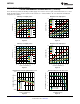
Simplified Application Schematic
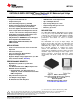
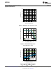
Connection Diagram
Figure 5. Top View - 11-Lead PFM
PIN DESCRIPTIONS
Pin Name Description
1, 2 VIN Supply input — Nominal operating range is 6V to 36V . A small amount of internal capacitance is contained within the
package assembly. Additional external input capacitance is required between this pin and PGND.
3, 5, AGND Analog Ground — Reference point for all stated voltages. Must be externally connected to EP/PGND.
6
4 EN Enable — Input to the precision enable comparator. Rising threshold is 1.274V typical. Once the module is enabled, a 20
uA source current is internally activated to accommodate programmable hysteresis.
7 FB Feedback — Internally connected to the regulation, over-voltage, and short-circuit comparators. The regulation reference
point is 0.8V at this input pin. Connect the feedback resistor divider between the output and AGND to set the output
voltage.
8 SS Soft-Start/Track input — To extend the 1.6 mSec internal soft-start connect an external soft start capacitor. For tracking
connect to an external resistive divider connected to a higher priority supply rail. See Design Steps for the LMZ13608
Application section.
9 NC No Connect. This pin must remain floating, do not ground.
10, VOUT Output Voltage — Output from the internal inductor. Connect the output capacitor between this pin and PGND.
11
EP PGND Exposed Pad / Power Ground Electrical path for the power circuits within the module. — NOT Internally connected to
AGND / pin 5. Used to dissipate heat from the package during operation. Must be electrically connected to pin 5 external
to the package.
Copyright © 2011–2013, Texas Instruments Incorporated Submit Documentation Feedback 3
Product Folder Links: LMZ13608