
Datasheet

LP3963, LP3966
www.ti.com
SNVS067H –APRIL 2000–REVISED APRIL 2013
LP3963/LP3966 3A Fast Ultra Low Dropout Linear Regulators
Check for Samples: LP3963, LP3966
1
FEATURES
DESCRIPTION
The LP3963/LP3966 series of fast ultra low-dropout
2
• Ultra Low Dropout Voltage
linear regulators operate from a +2.5V to +7.0V input
• Low Ground Pin Current
supply. Wide range of preset output voltage options
• Load Regulation of 0.06%
are available. These ultra low dropout linear
regulators respond very quickly to step changes in
• 15µA Quiescent Current in Shutdown Mode
load which makes them suitable for low voltage
• Specified Output Current of 3A DC
microprocessor applications. The LP3963/LP3966 are
• Available in DDPAK/TO-263 and TO-220
developed on a CMOS process which allows low
Packages
quiescent current operation independent of output
load current. This CMOS process also allows the
• Output Voltage Accuracy ± 1.5%
LP3963/LP3966 to operate under extremely low
• Error Flag Indicates Output Status (LP3963)
dropout conditions.
• Sense Option Improves Load Regulation
Dropout Voltage: Ultra low dropout voltage; typically
(LP3966)
80mV at 300mA load current and 800mV at 3A load
• Minimum Output Capacitor Requirements
current.
• Overtemperature/Overcurrent Protection
Ground Pin Current: Typically 6mA at 3A load
• −40°C to +125°C Junction Temperature Range
current.
Shutdown Mode: Typically 15µA quiescent current
APPLICATIONS
when the shutdown pin is pulled low.
• Microprocessor Power Supplies
Error Flag: Error flag goes low when the output
• GTL, GTL+, BTL, and SSTL Bus Terminators
voltage drops 10% below nominal value (for LP3963).
• Power Supplies for DSPs
SENSE: Sense pin improves regulation at remote
• SCSI Terminator
loads. (For LP3966)
• Post Regulators
Precision Output Voltage: Multiple output voltage
• High Efficiency Linear Regulators
options are available ranging from 1.2V to 5.0V and
adjustable (LP3966), with a specified accuracy of
• Battery Chargers
±1.5% at room temperature, and ±3.0% over all
• Other Battery Powered Applications
conditions (varying line, load, and temperature).
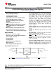
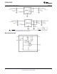
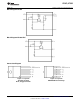
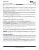
Typical Application Circuits
*SD and ERROR pins must be pulled high through a 10kΩ pull-up resistor. Connect the ERROR pin to ground if this
function is not used. See Application Hints for more information.
1
Please be aware that an important notice concerning availability, standard warranty, and use in critical applications of
Texas Instruments semiconductor products and disclaimers thereto appears at the end of this data sheet.
2All trademarks are the property of their respective owners.
PRODUCTION DATA information is current as of publication date.
Copyright © 2000–2013, Texas Instruments Incorporated
Products conform to specifications per the terms of the Texas
Instruments standard warranty. Production processing does not
necessarily include testing of all parameters.