MAX660 MAX660 Switched Capacitor Voltage Converter Literature Number: SNOS405
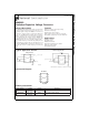
MAX660 Switched Capacitor Voltage Converter General Description Features The MAX660 CMOS charge-pump voltage converter inverts a positive voltage in the range of 1.5V to 5.5V to the corresponding negative voltage. The MAX660 uses two low cost capacitors to provide 100 mA of output current without the cost, size, and EMI related to inductor based converters.
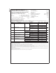
MAX660 Absolute Maximum Ratings (Note 1) Power Dissipation (TA = 25˚C) (Note 3) TJ Max (Note 3) θJA (Note 3) Operating Junction Temp. Range Storage Temperature Range Lead Temperature (Soldering, 10 seconds) ESD Rating If Military/Aerospace specified devices are required, please contact the National Semiconductor Sales Office/ Distributors for availability and specifications. Supply Voltage (V+ to GND, or GND to OUT) 6V LV (OUT − 0.3V) to (GND + 3V) FC, OSC The least negative of (OUT − 0.
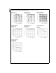
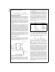
MAX660 Test Circuit DS100898-4 FIGURE 1. MAX660 Test Circuit Typical Performance Characteristics Supply Current vs Supply Voltage (Circuit of Figure 1) Supply Current vs Oscillator Frequency DS100898-36 Output Source Resistance vs Temperature Output Source Resistance vs Supply Voltage DS100898-38 DS100898-37 Efficiency vs Load Load Current DS100898-39 Output Voltage Drop vs Load Current DS100898-40 3 DS100898-41 www.national.
MAX660 Typical Performance Characteristics Efficiency vs Oscillator Frequency (Circuit of Figure 1) (Continued) Output Voltage vs Oscillator Frequency DS100898-13 Oscillator Frequency Supply Voltage (FC = V+) DS100898-14 Oscillator Frequency vs Supply Voltage (FC = Open) DS100898-16 DS100898-19 4 DS100898-15 Oscillator Frequency vs Temperature (FC = V+) DS100898-17 Oscillator Frequency vs Temperature (FC = Open) www.national.
MAX660 Pin Description Pin Name Function Voltage Inverter 1 FC Voltage Doubler Frequency control for internal oscillator: FC = open, fOSC = 10 kHz (typ); Same as inverter. FC = V+, fOSC = 80 kHz (typ); FC has no effect when OSC pin is driven externally. 2 CAP+ Connect this pin to the positive terminal of charge-pump capacitor. Same as inverter. 3 GND Power supply ground input. Power supply positive voltage input. 4 CAP− Connect this pin to the negative terminal of charge-pump capacitor.
MAX660 Application Information lows smaller capacitors to be used for equivalent output resistance and ripple, but increases the typical supply current from 0.12 mA to 1 mA. (Continued) The oscillator frequency can be lowered by adding an external capacitor between OSC and GND. (See Typical Performance Characteristics.) Also, in the inverter mode, an external clock that swings within 100 mV of V+ and GND can be used to drive OSC. Any CMOS logic gate is suitable for driving OSC.
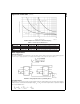
MAX660 Application Information (Continued) DS100898-32 FIGURE 4. Output Source Resistance vs Oscillator Frequency TABLE 2. Low ESR Capacitor Manufacturers Manufacturer Phone FAX Nichicon Corp. (708)-843-7500 (708)-843-2798 PL, PF series, through-hole aluminum electrolytic Capacitor Type AVX Corp.
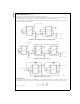
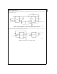
MAX660 Other Applications (Continued) A three-stage cascade circuit shown in Figure 7 generates −3Vin, from Vin. Cascading is also possible when devices are operating in doubling mode. In Figure 8, two devices are cascaded to generate 3Vin. An example of using the circuit in Figure 7 or Figure 8 is generating +15V or −15V from a +5V input.
(Continued) DS100898-11 FIGURE 9. Combining MAX660 with LP2951 to Make a Negative Adjustable Regulator Also, as shown in Figure 10 by operating MAX660 in voltage doubling mode and adding a linear regulator (such as LP2981) at the output, we can get +5V output from an input as low as +3V. DS100898-12 FIGURE 10. Generating +5V from +3V Input Voltage 9 www.national.com MAX660 Other Applications The error flag on pin 5 of the LP2951 goes low when the regulated output at pin 4 drops by about 5%.
MAX660 Other Applications (Continued) OTHER SWITCHED-CAPACITOR CONVERTERS Please refer to Table 3, which shows National’s Switched-Capacitor Converter products. TABLE 3. Switched-Capacitor Converters LM2664 LM2665 LM3350 LM3351 SOT23-6 SOT23-6 Mini SO-8 Mini SO-8 SO-8 0.22 0.22 3.75 1.1 0.12 at 10kHz, 1.0 at 80kHz Output Ω (typ.) 12 12 4.2 4.2 6.5 Oscillator (kHz) 80 80 800 200 10, 80 1.8 to 5.5 1.8 to 5.5 2.5 to 6.25 2.5 to 6.25 1.8 to 5.
MAX660 Switched Capacitor Voltage Converter Physical Dimensions inches (millimeters) unless otherwise noted 8-Lead SO (M) Order Number MAX660M NS Package Number M08A LIFE SUPPORT POLICY NATIONAL’S PRODUCTS ARE NOT AUTHORIZED FOR USE AS CRITICAL COMPONENTS IN LIFE SUPPORT DEVICES OR SYSTEMS WITHOUT THE EXPRESS WRITTEN APPROVAL OF THE PRESIDENT AND GENERAL COUNSEL OF NATIONAL SEMICONDUCTOR CORPORATION. As used herein: 1.
IMPORTANT NOTICE Texas Instruments Incorporated and its subsidiaries (TI) reserve the right to make corrections, modifications, enhancements, improvements, and other changes to its products and services at any time and to discontinue any product or service without notice. Customers should obtain the latest relevant information before placing orders and should verify that such information is current and complete.