
CCD Camera User's Guide MC-780PIx

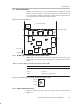

Rear Panel Switches and Terminals
2-4
Nomenclature and Use of Each Component
Table 2–2.External Synchronization Terminal Resistance Switch SW4
Switch Position Terminal Resistance Value
Left 75 Ω
Center 100 kΩ
Right
150 Ω
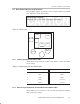
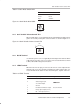
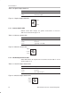
Figure 2–2. External Synchronization Terminal Resistance Switch SW4
Center
Left Right
Note:
When outputting internal sync signal, set the switch to 100 kΩ.
2.2.3 Mode Switches SW3
The SW3 mode switches control the functions listed in Table 2–2 and
Table 2–4.
Table 2–3.Mode Switches SW3
Switch No. Mode Operation
1 Shutter 1 Refer to list below
2 Shutter 2 Refer to list below
3 External sync ON for external sync
4 External sync ON for external sync
5 Interlace/noninterlace ON for interlace
6
Not used
Table 2–4.Shutter list
Shutter 1 Shutter 2 Mode
OFF OFF Shutter OFF (1/60 sec. exposure)
ON OFF Continuous shutter, see Note 1
ON ON Continuous shutter, see Note 2
OFF
ON V.I. (Variable Integration)
Notes: 1) V reset not done when external trigger is input.
2) V reset done when external trigger is input.
2.2.4 Gain Mode Switch SW2
Gain mode switch SW2 controls the gain as shown in Table 2–5 and
Figure 2–3.