
CCD Camera User's Guide MC-780PIx


Gain Variable Volume Control VR1
2-5
Nomenclature and Use of Each Component
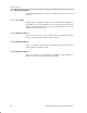
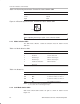
Table 2–5.Gain Mode Switch SW2
Switch No. Gain Mode
Left AGC
Center Fixed
Right
Variable
Figure 2–3. Gain Mode Switch SW2
Center
Left Right
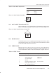
2.2.5 Gain Variable Volume Control VR1
When variable gain is selected with gain mode switch SW2 in the right position,
gain is increased by turning VR1 counterclockwise as shown in Figure 2–4.
Figure 2–4. Gain Variable Volume Control VR1
UP
2.2.6 DC IN Terminal
Use when the power source is supplied by the AC adaptor: PS-780-12J. When
a different type of power source is used, the connector standard must conform
to EIAJ, RC-5320A Voltage Classification 4.
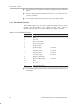
2.2.7 LENS Terminal
When the auto-iris lens plug is connected, the lens iris can be adjusted auto-
matically. This is also the terminal for inputting the shutter trigger cable con-
nector: HR10A-7P–6P. Table 2–6 lists the terminal pins, signals, and levels.
Table 2–6.LENS Terminal
Pin No. Input Signal Signal Level
1 Field index output Good for HC125
2
Shutter trigger input
CMOS level
VI command input
CMOS
l
eve
l
3 Ground
4 Readout field indicator output Good for HC125
5 Image signal output (for iris)
6
DC + 12V output (for lens)