
CCD Camera User's Guide MC-780PIx


DC IN/SYNC Terminal
2-6
Nomenclature and Use of Each Component
The odd fields are low and the even fields are high for the pin 1 field index
output.
The pin 5 image signal is provided for auto-iris use so it cannot be con-
nected to a monitor.
The dc voltage output from pin 6 is the same as the input voltage.
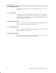
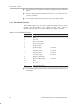
2.2.8 DC IN/SYNC Terminal
This terminal supplies the +12 V power, outputs the image from the camera
module, and inputs/outputs sync signals, through cable connector
HR10A–10P–12S. Table 2–7 lists the terminal pins, signals, and levels.
Table 2–7.DC IN/SYNC Terminal
Pin No. Input/Output Signal Signal Level
1 GND
2 DC + 12V
3 Image output (GND)
4 Image output (signal)
5 HD input/output
6
HD input (signal) For HCT14
HD output (signal) For HC125
7
VD input (signal) For HCT14
VD output (signal) For HC125
8 Optional output (GND)
9 Optional output (signal) For HC126
10 GND
11 DC + 12V
12
VD input/output (GND)
The optional outputs on pins 8 and 9 select shutter monitor output or pixel
clock output.