
CCD Camera User's Guide MC-780PIx


Internal Switches
2-7
Nomenclature and Use of Each Component
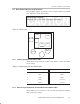
2.3 Internal Switches
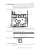
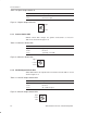
Remove the camera cover to set the internal switches. Viewing the camera
from the front, the switches are located on boards in the center and the left.
The center board is called the clock board, and the left board is called the pro-
cess board. Figure 2–5 shows the switch locations.
Figure 2–5. Internal Switches
(HD/VD
SW1)
(S1)
(ϒ SW1)
(SW2)
(SW4)
Clock board inside
Clock board outside
Connectors
Bottom
Lens
Processor board outside
2.3.1 SYNC Signal (HD/VD) Input/Output Switch SW1
Switch SW1 selects between internal sync output and external sync input.
Table 2–8 lists the switch positions and functions, and Figure 2–6 shows the
switch.
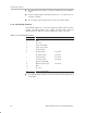
Table 2–8.SYNC Signal (HD/VD) Input/Output Switch SW1
Switch Position Input/Output Mode
Upper External sync signal input
Center Not used
Lower
Internal sync signal output
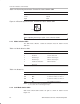
Figure 2–6. SYNC Signal (HD/VD) Input/Output Switch SW1
Upper
Center
Lower
2.3.2 Option Output Switch S1
Switch S1 switches the option output as listed in Table 2–9 and shown in
Figure 2–7.