
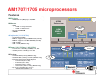
Computer Accessories User Manual


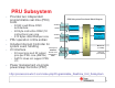


PRU Subsystem
•
Provides two independent
PRU0 Core
DRAM0
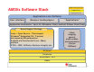
PRU Subsystem Functional Block Diagram
32 GPO
•
Provides two independent
programmable real-time (PRU)
cores
•
32
-
Bit Load/Store RISC
architecture
32-
bit Interconnect SCR
PRU0 Core
PRU1 Core
DRAM0
(512 Bytes)
DRAM1
(512 Bytes)
4KB IRAM
30 GPI
32 GPO
30 GPI
•
32
-
Bit Load/Store RISC
architecture
• 4K Byte instruction RAM (1K
instructions) per core
•
512 Bytes data RAM per core
bit Interconnect SCR
Master I/F
(to SCR2)
4KB IRAM
Interrupts to
ARM INTC
30 GPI
•
512 Bytes data RAM per core
• PRU operation is little endian
• Includes Interrupt Controller for
system event handling
•
I/O interface
bit Interconnect SCR
Interrupt
Controller
(INTC)
Slave I/F
(from SCR2)
ARM INTC
Events from
Peripherals +
PRUs
•
I/O interface
• 30 input pins and 32 output
pins per PRU core (AM18x)
•
AM17x does not support PRU
I/O
AM17x does not support PRU
I/O
• Power management via single
power/sleep controller (PSC)
http://processors.wiki.ti.com/index.php/Programmable_Realtime_Unit_Subsystem
26