User's Guide SLAU597 – March 2015 MSP‑EXP432P401R LaunchPad™ Evaluation Kit The MSP‑EXP432P401R LaunchPad™ is an easy-to-use Evaluation Module (EVM) for the MSP432P401R microcontroller. It contains everything needed to start developing on the MSP432 LowPower + Performance ARM® 32-bit Cortex®-M4F microcontroller (MCU), including on-board emulation for programming, debugging, and energy measurements.
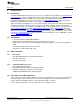
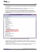
www.ti.com 1 2 3 4 5 6 Contents Getting Started ............................................................................................................... 3 Hardware...................................................................................................................... 5 Software Examples ........................................................................................................ 17 Resources ...................................................................................
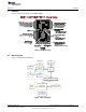
Getting Started www.ti.com 1 Getting Started 1.1 Introduction The MSP‑EXP432P401R LaunchPad is an easy-to-use evaluation module (EVM) for the MSP432P401R microcontroller. It contains everything needed to start developing on the MSP432 Low-Power + Performance ARM 32-bit Cortex-M4F microcontroller (MCU), including on-board emulation for programming, debugging, and energy measurements.
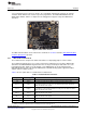
Getting Started 1.5 www.ti.com Next Steps: Looking Into the Provided Code It is now time to start exploring more features of the EVM! www.ti.com/beginMSP432launchpad To get started, you will need an integrated development environment (IDE) to explore and start editing the code examples. Refer to Section 4 for more information on IDEs and where to download them. The out-of-box source code and more code examples are provided for download at http://www.ti.com/tool/msp-exp432p401r.
Hardware www.ti.com 2 Hardware Figure 2 shows an overview of the EVM hardware. Figure 2. EVM Overview 2.1 Block Diagram Figure 3 shows the block diagram. Micro‐B USB LED Red, Green ESD Protection EnergyTrace+ Current Measure HW Debug MCU LDO 5 V, 3.3 V Power Switch Power, UART, SWD to Target Crystal 48 MHz Target Device MSP432P401R 40‐pin LaunchPad standard headers User Interface Buttons and LEDs Figure 3.
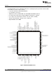
Hardware 2.2 www.ti.com MSP432P401R P6.2/UCB1STE/C1.5 P6.3/UCB1CLK/C1.4 P6.4/UCB1SIMO/UCB1SDA/C1.3 P6.5/UCB1SOMI/UCB1SCL/C1.2 P6.6/TA2.3/UCB3SIMO/UCB3SDA/C1.1 P6.7/TA2.4/UCB3SOMI/UCB3SCL/C1.0 DVSS3 RSTn/NMI AVSS2 PJ.2/HFXOUT PJ.3/HFXIN AVCC2 P7.0/PM_SMCLK/PM_DMAE0 P7.1/PM_C0OUT/PM_TA0CLK P7.2/PM_C1OUT/PM_TA1CLK P7.3/PM_TA0.0 PJ.4/TDI/ADC14CLK PJ.5/TDO/SWO SWDIOTMS SWCLKTCK P9.4/UCA3STE P9.5/UCA3CLK P9.6/UCA3RXD/UCA3SOMI P9.7/UCA3TXD/UCA3SIMO P10.
Hardware www.ti.com 2.3 XDS110-ET Onboard Emulator To keep development easy and cost effective, TI's LaunchPad evaluation kits integrate an onboard emulator, which eliminates the need for expensive programmers. The MSP‑EXP432P401R has the XDS110-ET emulator, which is a simple low-cost debugger that supports nearly all TI ARM device derivatives. Figure 5. XDS110-ET Emulator The XDS110-ET hardware can be found in the schematics in Section 6 and in the MSP‑EXP432P401R Hardware Design Files zip folder. 2.3.
Hardware www.ti.com Table 1. Isolation Block Connections (continued) Signal Isolation Type (1) (2) TMS_SWDIO Switch S101 Serial wire data input/output (SWDIO) / JTAG test mode select (TMS) TDO_SWO Switch S101 Serial wire trace output (SWO) / JTAG trace output (TWO) (Also PJ.5) TDI Switch* S101 JTAG test data input (Also PJ.
Hardware www.ti.com The backchannel UART allows communication with the USB host that is not part of the target application's main functionality. This is very useful during development, and also provides a communication channel to the PC host side. This can be used to create GUIs and other programs on the PC that communicate with the LaunchPad. The pathway of the backchannel UART is shown in Figure 7. The backchannel UART eUSCI_A0 is independent of the UART on the 40-pin BoosterPack connector eUSCI_A2.
Hardware www.ti.com The XDS110-ET also supports hardware flow control, if desired. Hardware flow control (CTS and RTS handshaking) allows the target MSP432P401R and the emulator to tell each other to wait before sending more data. At low baud rates and with simple target applications, flow control may not be necessary. Applications with higher baud rates and more interrupts to service have a higher likelihood that the will not be able to read the eUSCI_A0 buffer in time, before the next byte arrives.
Hardware www.ti.com Figure 8.
Hardware www.ti.com Starting a debug session will now open EnergyTrace technology windows. These windows show energy, power, profile, and states to give the user a full view of the energy profile of their application. Figure 9. EnergyTrace Windows This data allows the user to see exactly where and how energy is consumed in their application. Optimizations for energy can be quickly made for the lowest power application possible.
Hardware www.ti.com 2.4 Power The board was designed to accommodate various powering methods, including through the on-board XDS110-ET and from an external source or BoosterPack. Figure 10. MSP‑‑EXP432P401R Power Block Diagram 2.4.1 XDS110-ET USB Power The most common power-supply scenario is from USB through the XDS110-ET debugger. This provides 5-V power from the USB and also regulates this power rail to 3.3 V for XDS110-ET operation and 3.3 V to the target side of the LaunchPad.
Hardware 2.5 www.ti.com Measure MSP432 Current Draw To measure the current draw of the MSP432P401R, use the 3V3 jumper on the jumper isolation block. The current measured includes the target device and any current drawn through the BoosterPack headers. To measure ultra-low power, follow these steps: 1. Remove the 3V3 jumper in the isolation block, and attach an ammeter across this jumper. 2.
Hardware www.ti.com 2.7 BoosterPack Pinout The MSP‑EXP432P401R LaunchPad adheres to the 40-pin LaunchPad pinout standard. A standard was created to aid compatibility between LaunchPad and BoosterPack tools across the TI ecosystem. The 40-pin standard is compatible with the 20-pin standard that is used by other LaunchPads like the MSP‑EXP430FR4133. This allows some subset of functionality of 40-pin BoosterPacks to be used with 20-pin LaunchPads.
Hardware www.ti.com Figure 11. LaunchPad to BoosterPack Connector Pinout 2.8 2.8.1 Design Files Hardware Design Files Schematics can be found in Section 6. All design files including schematics, layout, bill of materials (BOM), Gerber files, and documentation are available in the MSP‑EXP432P401R Hardware Design Files zip folder.
Hardware www.ti.com 2.8.2 Software Examples All design files including TI-TXT object-code firmware images, software example projects, and documentation are available in the MSP‑EXP432P401R Software Examples zip folder. 2.9 Hardware Change Log Table 3. Hardware Change Log 3 PCB Revision Date Description Rev 1.
Software Examples www.ti.com A PC GUI accompanies the out-of-box demo to allow user to set the color and blink rate of the RGB LED. If not already, connect the LaunchPad using the included USB cable to a computer. The out-of-box GUI can be opened from within CCS using the TI Resource Explorer: MSPWare > Development Tools > MSP‑EXP432P401R > Examples > Out of Box Experience GUI. A copy can also be found in the MSP‑EXP432P401R Software Examples zip download. Figure 12.
Software Examples www.ti.com Figure 13. Out-of-Box GUI Running From TI Cloud Tools Click on the Connect button to connect to the LaunchPad then open the serial COM port. Once the connection has been established and the GUI indicates, “Target Status: Running…,” you can use the color wheel or the Red, Green, and Blue color sliders to set the color of the LaunchPad RGB LED. Changing the LED Beats Per Minute input box sets the RGB LED blink rate. 3.
Software Examples 3.2.1 www.ti.com Source File Structure The project is split into multiple files. This makes it easier to navigate and reuse parts of it for other projects. Table 6. Source File and Folders Name 3.2.2 Description main.c The demo's main function, shared ISRs, and so on sl_common.
Software Examples www.ti.com 3.2.3 Overview of Backend Servers Figure 14. Backend Block Diagram of CC3100BOOST MQTT-Twitter LED Control Demo As shown in the above Figure 14, inputs from either the MSP432 LaunchPad or Twitter travel through a couple of intermediary servers before reaching the output on the opposite end. Instead of interacting with Twitter server directly through the more resource intensive HTTP, the MSP432 LaunchPad communicates with the cloud solely through MQTT protocol.
Software Examples 3.3 www.ti.com BOOSTXL-K350QVG-S1 Graphics Library Example This software is available in the MSP‑EXP432P401R Software Examples zip download, or more easily accessible through MSPWare (see Section 4.3). The demo shows how to use the MSP Graphics Library http://www.ti.com/tool/msp-grlib or “grlib,” in a project with the Kentec display. This demo shows the user how to enable the touch screen, create buttons, and use graphics primitives including colors and images.
Software Examples www.ti.com Figure 15. Importing and Converting an Image With MSP Image Reformer 3.4 430BOOST-SHARP96 Graphics Library Example This software example is similar to the BOOSTXL-K350QVG-S1 Graphics library example. It shows how to use the MSP Graphics Library http://www.ti.com/tool/msp-grlib or “grlib,” in a project with the Sharp 96×96 display. The Sharp 96×96 display BoosterPack does not support touch or color, it is a simple monochrome LCD.
Resources www.ti.com 4 Resources 4.1 Integrated Development Environments Although the source files can be viewed with any text editor, more can be done with the projects if they're opened with a development environment like Code Composer Studio™ (CCS), Keil™ uVision®, IAR Embedded Workbench®, or Energia. 4.1.1 TI Cloud Development Tools TI's Cloud-based software development tools provide instant access to MSPWare content and a webbased IDE. 4.1.1.
Resources www.ti.com 4.1.4 IAR Embedded Workbench for ARM IAR Embedded Workbench for ARM is another very powerful integrated development environment that allows you to develop and manage complete embedded application projects. It integrates the IAR C/C++ Compiler, IAR Assembler, IAR ILINK Linker, editor, project manager, command line build utility, and IAR C-SPY Debugger. Note: MSP432 LaunchPad requires IAR Embedded Workbench for ARM Version 7.10 or later. Refer to the IAR Embedded Workbench for ARM 7.
Resources www.ti.com Figure 16. Using TI Resource Explorer to Browse MSP‑‑EXP432P401R in MSPWare Inside TI Resource Explorer, these examples and many more can be found, and easily imported into CCS with one click.
Resources www.ti.com 4.4 4.4.1 MSP432P401R Device Documentation At some point, you will probably want more information about the MSP432P401R device. For every MSP device, the documentation is organized as shown in Table 7. Table 7. How MSP Device Documentation is Organized Document Device family user's guide Device-specific data sheet 4.4.
FAQ 5 www.ti.com FAQ Q: I can't program my LaunchPad; the IDE can't connect to target. What's wrong? A: Check the following: • Is the JTAG switch (S101) in the correct orientation? – Switch to left for XDS110-ET onboard debugger – Switch to the right for external debugger connection • If using an external debugger, is USB power provided? • Check the debugger settings: change to Serial Wire Debug (SWD) without SWO – Under targetconfigs double-click the *.
FAQ www.ti.com – Right click Launch Selected Configuration. Figure 19. Launch Selected Configuration – The debugger will now connect to your device (which is still possible), but does not try to halt the CPU, write to registers or even download code (which would not be possible). The Debug view that is spawned shows the CPU core, but marks it as disconnected. – Right click Show all cores. Figure 20.
FAQ www.ti.com The MSP432 Debug Access Port, or DAP, is shown under Non Debuggable devices. – Right click Connect Target Figure 21. Connect Target Now a script needs to be run to return the device back to factory settings Scripts > default > MSP432_Factory_Reset Figure 22. MSP432_Factory_Reset Script • 30 These instructions are generally the same for all IDEs, but the exact steps may vary slightly by IDE.
FAQ www.ti.com Q: How do I use the LaunchPad and my Segger J-Link to debug the target externally? It won't connect to the onboard connector. A: The Segger J-Link is the only major ARM debugger that doesn't come with an adapter for the 10-pin small pitch ARM connector.
MSP‑EXP432P401R LaunchPad™ Evaluation Kit Copyright © 2015, Texas Instruments Incorporated D C B 1 88 89 90 91 26 27 28 29 54 55 76 77 78 79 80 81 64 65 66 67 68 69 70 71 56 57 58 59 60 61 62 63 32 33 34 35 36 37 38 39 16 17 18 19 20 21 22 23 4 5 6 7 8 9 10 11 2 P7.0/PM_SMCLK/PM_DMAE0 P7.1/PM_C0OUT/PM_TA0CLK P7.2/PM_C1OUT/PM_TA1CLK P7.3/PM_TA0.0 P7.4/PM_TA1.4/C0.5 P7.5/PM_TA1.3/C0.4 P7.6/PM_TA1.2/C0.3 P7.7/PM_TA1.1/C0.2 P6.0/A15 P6.1/A14 P6.2/UCB1STE/C1.5 P6.3/UCB1CLK/C1.4 P6.
Schematics D D 6 C C B 5 2 4 3 3 4 1 2 1 1 2 5 1 2 3 1 2 3 6 A www.ti.com 2 2 1 2 1 2 1 2 1 B A 1 1 2 Figure 24.
MSP‑EXP432P401R LaunchPad™ Evaluation Kit Copyright © 2015, Texas Instruments Incorporated D C B 1 1 2 3 4 5 6 7 8 9 10 1 2 1 2 1 2 1 2 1 2 34 1 2 A 1 2 2 21 22 23 24 25 26 27 28 29 30 3 3 4 4 40 39 38 37 36 35 34 33 32 31 1 3 5 7 9 11 13 15 17 19 21 23 25 27 29 31 33 35 37 5 1 3 5 7 9 11 13 15 17 19 21 23 25 27 29 31 33 35 37 5 2 4 6 8 10 12 14 16 18 20 22 24 26 28 30 32 34 36 38 2 4 6 8 10 12 14 16 18 20 22 24 26 28 30 32 34 36 38 20 19 18 17 16 15 14 13 12 11 6 6 D C B A S
Copyright © 2015, Texas Instruments Incorporated D C B 1 P$118 P$119 P$103 P$104 P$105 P$106 P$78 P$77 P$76 P$75 P$74 P$73 P$72 P$71 P$18 P$19 P$20 P$21 P$63 P$62 P$61 P$60 P$116 P$117 P$49 P$50 P$15 P$14 P$13 P$12 P$123 P$124 P$100 P$99 P$98 P$97 P$25 P$24 P$23 P$22 PP0 PP1 PP2 PP3 PP4 PP5 PM0 PM1 PM2 PM3 PM4 PM5 PM6 PM7 PK0 PK1 PK2 PK3 PK4 PK5 PK6 PK7 PJ0 PJ1 PG0 PG1 PE0 PE1 PE2 PE3 PE4 PE5 PC0 PC1 PC2 PC3 PC4 PC5 PC6 PC7 2 PQ0 PQ1 PQ2 PQ3 PQ4 PN0 PN1 PN2 PN3 PN4 PN5 PL0 PL1 PL2 PL3
Schematics 4 5 4 3 2 1 D C B A 1 2 1 2 3 4 5 6 7 8 3 TP 16 15 14 13 12 11 10 9 4 5 5 3 1 IN1 OUT IN2 EN GND 2 6 D C B 6 A www.ti.com Figure 27.
Copyright © 2015, Texas Instruments Incorporated D C B 1 1 2 3 3 5 8 1 2 3 NR EN IN IO1 VCC IO2 IO4 GND IO3 2 6 5 4 GND PAD SLAU597 – March 2015 Submit Documentation Feedback 2 IN GND OUT 4 9 A GND NC D+ DVBUS 1 NC2 NC1 NC0 OUT 1 7 6 2 EN NC NC_2 3 6 5 4 3 1 2 3 4 5 6 7 8 9 10 11 12 13 14 15 16 4 REFCLK NXT DATA0 DATA1 DATA2 DATA3 DATA4 NC_2 DATA5 DATA6 CS VDD15 DATA7 CFG NC_3 NC_4 4 5 EPAD VDDIO DIR VDD18 STP VDD18_2 RESETB CLOCK NC NC_5 ID VBUS VBAT VDD33 DM DP CPEN 5
MSP‑EXP432P401R LaunchPad™ Evaluation Kit Copyright © 2015, Texas Instruments Incorporated D C B A 1 1 2 6 7 8 9 3 2 11 10 6 7 8 9 3 2 11 10 6 7 8 9 3 2 11 10 2 1B1 1B2 2B1 2B2 1B1 1B2 2B1 2B2 1A1 1A2 2A1 2A2 1B1 1B2 2B1 2B2 VCCA *1OE VCCB *2OE GND 1DIR GND_2 2DIR 1A1 1A2 2A1 2A2 VCCA *1OE VCCB *2OE GND 1DIR GND_2 2DIR 1A1 1A2 2A1 2A2 VCCA *1OE VCCB *2OE GND 1DIR GND_2 2DIR 15 14 13 12 1 16 4 5 15 14 13 12 1 16 4 5 15 14 13 12 1 16 4 5 3 3 4 1 3 5 7 9 4 2 4 6 8 10 10
IMPORTANT NOTICE Texas Instruments Incorporated and its subsidiaries (TI) reserve the right to make corrections, enhancements, improvements and other changes to its semiconductor products and services per JESD46, latest issue, and to discontinue any product or service per JESD48, latest issue. Buyers should obtain the latest relevant information before placing orders and should verify that such information is current and complete.