
User manual

Hardware
www.ti.com
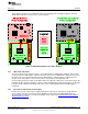
2.5 Measure MSP432 Current Draw
To measure the current draw of the MSP432P401R, use the 3V3 jumper on the jumper isolation block.
The current measured includes the target device and any current drawn through the BoosterPack
headers.
To measure ultra-low power, follow these steps:
1. Remove the 3V3 jumper in the isolation block, and attach an ammeter across this jumper.
2. Consider the effect that the backchannel UART and any circuitry attached to the MSP432P401R may
have on current draw. Disconnect these at the isolation block if possible, or at least consider their
current sinking and sourcing capability in the final measurement.
3. Make sure there are no floating input I/Os. These cause unnecessary extra current draw. Every I/O
should either be driven out or, if it is an input, should be pulled or driven to a high or low level.
4. Begin target execution.
5. Measure the current. Keep in mind that if the current levels are fluctuating, it may be difficult to get a
stable measurement. It is easier to measure quiescent states.
For a better look at the power consumed in the application, use EnergyTrace+ Technology. EnergyTrace+
Technology allows the user to see energy consumed as the application progresses. More details about
EnergyTrace+ Technology can be found in Section 2.3.5.
2.6 Clocking
The MSP‑EXP432P401R provides external clocks in addition to the internal clocks in the device.
• Q1: 32-kHz crystal (LFXTCLK)
• Q2: 48-MHz crystal (HFXTCLK)
The 32-kHz crystal allows for lower LPM3 sleep currents, and higher precision clock source than the
default internal 32 kHz REFOCLK. Therefore, the presence of the crystal allows the full range of low-
power modes to be used.
The 48-MHz crystal allows the device to run at its maximum operating speed for MCLK and HSMCLK.
The MSP432P401R device has several internal clocks that can be sourced from many clock sources.
Most peripherals on the device can select which of the internal clocks to use to operate at the desired
speed.
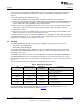
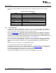
The internal clocks in the device default to the configuration listed in Table 2.
Table 2. Default Clock Operation
Clock Default Clock Source Default Clock Description
Frequency
Master Clock
MCLK DCO 3 MHz
Sources CPU and peripherals
Subsystem Master Clock
HSMCLK DCO 3 MHz
Sources peripherals
Low-speed subsystem master clock
SMCLK DCO 3 MHz
Sources peripherals
LFXT (or REFO if no Auxiliary clock
ACLK 32.768 kHz
crystal present) Sources peripherals
LFXT(or REFO if no Low-speed backup domain clock
BCLK 32.768 kHz
crystal present) Sources LPM peripherals
For more information about configuring internal clocks and using the external oscillators, see the
MSP432P4xx Family Technical Reference Manual SLAU356.
14
MSP
‑
EXP432P401R LaunchPad™ Evaluation Kit SLAU597–March 2015
Submit Documentation Feedback
Copyright © 2015, Texas Instruments Incorporated