
User manual

www.ti.com
Hardware
2.3 XDS110-ET Onboard Emulator
To keep development easy and cost effective, TI's LaunchPad evaluation kits integrate an onboard
emulator, which eliminates the need for expensive programmers. The MSP‑EXP432P401R has the
XDS110-ET emulator, which is a simple low-cost debugger that supports nearly all TI ARM device
derivatives.
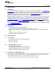
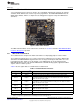
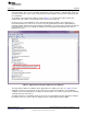
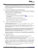
Figure 5. XDS110-ET Emulator
The XDS110-ET hardware can be found in the schematics in Section 6 and in the MSP‑EXP432P401R
Hardware Design Files zip folder.
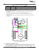
2.3.1 XDS110-ET Isolation Block
The isolation block is comprised of switch S101 and the accompanying jumpers next the switch.
The isolation block allows the user to connect or disconnect signals that cross from the XDS110-ET
domain into the MSP432P401R target domain. This crossing is shown by the dotted line across the
LaunchPad. No other signals cross this domain, so the XDS110-ET can be decoupled from the
MSP432P401R target side. This includes XDS110-ET Serial Wire Debug signals, application UART
signals, and 3.3-V and 5-V power.
Table 1 lists the signals that are controlled at the isolation block.
Table 1. Isolation Block Connections
Signal Isolation Type
(1)(2)
Description
5V Jumper 5-V power rail, VBUS from USB
3V3 Jumper 3.3-V power rail, derived from VBUS by an LDO in the XDS110-ET domain
Backchannel UART: Ready-To-Send, for hardware flow control. The target can use
RTS >> Jumper* this to indicate whether it is ready to receive data from the host PC. The arrows
indicate the direction of the signal.
Backchannel UART: Clear-To-Send, for hardware flow control. The host PC (through
CTS << Jumper* the emulator) uses this to indicate whether it is ready to receive data. The arrows
indicate the direction of the signal.
Backchannel UART: The target MCU receives data through this signal. The arrows
RXD << Jumper
indicate the direction of the signal.
Backchannel UART: The target MCU sends data through this signal. The arrows
TXD >> Jumper
indicate the direction of the signal.
RST Switch S101 MCU RST signal (active low)
TCK_SWCLK Switch S101 Serial wire clock input (SWCLK) / JTAG clock input (TCK)
(1)
Jumper* corresponds to signals without a jumper placed by default.
(2)
Switch* corresponds to signals that are controlled by S101, but not through IC111.
7
SLAU597–March 2015 MSP
‑
EXP432P401R LaunchPad™ Evaluation Kit
Submit Documentation Feedback
Copyright © 2015, Texas Instruments Incorporated