
User manual
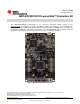
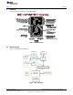
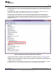

XDS110-ET
Emulator MCU
Isolation
Block
JTAG and SWD
Application UART
3.3V Power
5V Power
MSP432P401R
Target MCU
XDS110-ETMSP432 Target
USB Connector
in out
LDO
BoosterPack Header
BoosterPack Header
USB
EnergyTrace
S101
eUSCI_A0
Hardware
www.ti.com
Table 1. Isolation Block Connections (continued)
Signal Isolation Type
(1)(2)
Description
TMS_SWDIO Switch S101 Serial wire data input/output (SWDIO) / JTAG test mode select (TMS)
TDO_SWO Switch S101 Serial wire trace output (SWO) / JTAG trace output (TWO) (Also PJ.5)
TDI Switch* S101 JTAG test data input (Also PJ.4)
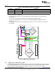
Reasons to open these connections:
• To remove any and all influence from the XDS110-ET emulator for high accuracy target power
measurements
• To control 3-V and 5-V power flow between the XDS110-ET and target domains
• To expose the target MCU pins for other use than onboard debugging and application UART
communication
• To expose the UART interface of the XDS110-ET so that it can be used for devices other than the
onboard MCU.
Figure 6. XDS110-ET Isolation Block
2.3.2 Application (or “Backchannel”) UART
The XDS110-ET provides a “backchannel” UART-over-USB connection with the host, which can be very
useful during debugging and for easy communication with a PC. The provided UART supports hardware
flow control (RTS and CTS); although by default these signals are not connected to the target.
8
MSP
‑
EXP432P401R LaunchPad™ Evaluation Kit SLAU597–March 2015
Submit Documentation Feedback
Copyright © 2015, Texas Instruments Incorporated