
Manual
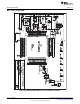
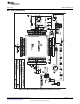
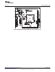

Connector J5
External power connector
Jumper JP1 to "ext"
Jumper JP1
Open to measure current
Orient Pin 1 of MSP430 device
Jumpers JP5 to JP10
Close 1-2 to debug in Spy-Bi-Wire mode
Close 2-3 to debug in 4-wire JTAG mode
JP11, JP12, JP13
Connect 1-2 to connect
AUXVCCx with DVCC or
drive AUXVCCx externally
D1 LED connected to P1.0
Jumper JP2
Open to disconnect LED
www.ti.com
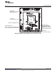
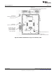
MSP-TS430PZ100B
Figure B-46. MSP-TS430PZ100B Target Socket Module, PCB
103
SLAU278F–May 2009–Revised December 2010 Hardware
Submit Documentation Feedback
© 2009–2010, Texas Instruments Incorporated