User’s Guide July 2009 SLAU048H
EVALUATION BOARD/KIT IMPORTANT NOTICE Texas Instruments (TI) provides the enclosed product(s) under the following conditions:. This evaluation board/kit is intended for use for ENGINEERING DEVELOPMENT, DEMONSTRATION, OR EVALUATION PURPOSES ONLY and is not considered by TI to be a finished end−product fit for general consumer use. Persons handling the product(s) must have electronics training and observe good engineering practice standards.
EVM WARNINGS AND RESTRICTIONS It is important to operate this EVM within the specified input and output ranges described in the EVM User’s Guide. Exceeding the specified input range may cause unexpected operation and/or irreversible damage to the EVM. If there are questions concerning the input range, please contact a TI field representative prior to connecting the input power.
Trademarks Preface About This Manual This document describes the MSP430-family hardware, operation, and software installation and setup. How to Use This Manual This document contains the following chapters: - Chapter 1 − Installation and Setup - Chapter 2 − Operation - Chapter 3 − Hardware - Appendix A − Hex Object Format - Appendix B − Schematics Notational Conventions This document uses the following conventions.
FCC Warning FCC Warning This evaluation board/kit is intended for use for ENGINEERING DEVELOPMENT, DEMONSTRATION, OR EVALUATION PURPOSES ONLY and is not considered by TI to be a finished end-product fit for general consumer use. It generates, uses, and can radiate radio frequency energy and has not been tested for compliance with the limits of computing devices pursuant to part 15 of FCC rules, which are designed to provide reasonable protection against radio frequency interference.
Running Title—Attribute Reference 1 Installation and Setup . . . . . . . . . . . . . . . . . . . . . . . . . . . . . . . . . . . . . . . . . . . . . . . . . . . . . . . . . . . . 1-1 1.1 Installing the Software . . . . . . . . . . . . . . . . . . . . . . . . . . . . . . . . . . . . . . . . . . . . . . . . . . . . . . . 1-2 1.2 Installing the Hardware . . . . . . . . . . . . . . . . . . . . . . . . . . . . . . . . . . . . . . . . . . . . . . . . . . . . . . 1-3 2 Operation . . . . . . . . . . . . .
Running Title—Attribute Reference 1−1 1−2 2−1 2−2 2−3 2−4 2−5 3−1 3−2 3−3 3−4 3−5 A−1 ADT430 Program Icons . . . . . . . . . . . . . . . . . . . . . . . . . . . . . . . . . . . . . . . . . . . . . . . . . . . . . . . . 1-2 Serial Programming Adapter . . . . . . . . . . . . . . . . . . . . . . . . . . . . . . . . . . . . . . . . . . . . . . . . . . . . 1-3 MSP430 Programmer Dialog Box . . . . . . . . . . . . . . . . . . . . . . . . . . . . . . . . . . . . . . . . . . . . . . .
Chapter 1 This chapter describes the process of installing and programming the hardware and software for the MSP430-PRGS430 programming adapter used with the MSP430 family of microcontrollers. Topic Page 1.1 Installing the Software . . . . . . . . . . . . . . . . . . . . . . . . . . . . . . . . . . . . . . . . . 1-2 1.2 Installing the Hardware . . . . . . . . . . . . . . . . . . . . . . . . . . . . . . . . . . . . . . . .
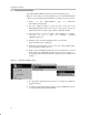
Installing the Software 1.1 Installing the Software To install the MSP-PRGS430 software, perform the following steps: NOTE: To ensure that you are using the latest version of the MSP-PRGS430 software, you must download the installation executable from the TI web site. 1) Browse to the MSP-PRGS430 (http://www.ti.com/prgs430). page on www.ti.
Installing the Hardware 1.2 Installing the Hardware To install the programming adapter hardware, perform the following steps: 1) Using the 9-pin SUB-D connector, connect the programming adapter to the serial port (COM1−COM4) of the PC. 2) Connect an external power supply to the programming adapter. The voltage of the power supply must be between 14 V and 20 V dc and must provide a minimum of 200 mA of power. The center terminal of the supply connector at the programming adapter is the plus pole.
1-4
Chapter 2 This chapter describes the programming procedure for MSP430 devices and the error messages you may encounter during the procedure. Topic Page 2.1 Software/Hardware Layers of the PRGS430 Environment . . . . . . . . . 2-2 2.2 Programming MSP430 Devices With the GUI . . . . . . . . . . . . . . . . . . . . 2-3 2.3 Command Line Options . . . . . . . . . . . . . . . . . . . . . . . . . . . . . . . . . . . . . . 2-10 2.4 PRGS430.DLL—Description . . . . . . . . . . . . . . . . . . . .
Software/Hardware Layers of the PRGS430 Environment 2.1 Software/Hardware Layers of the PRGS430 Environment PC − Software GUI PRGS430.EXE PRGS430.INI CommandLine Function DEVICE.CFG PRGS430.DLL [Project] .INI RS232 PRGS430 Serial Programming Adapter JTAG MSP430 Target Socket or Application There are three ways to handle and communicate with the PRGS430 hardware: - Using the graphical user interface (see Section 2.2) - Using command line parameters (see Section 2.3) - Using the PRGS430.
Programming MSP430 Devices With the GUI 2.2 Programming MSP430 Devices With the GUI 2.2.1 Basic Procedure The following steps should be used to program the MSP430 devices: 1) Click on the Program Device icon during the installation-selected program group (default: ADT430). The MSP430 programmer dialog box appears. The status line at the bottom of the window shows the actual or the most recent activity (see Figure 2−1). The status line displays the message Connecting to adapter...
Programming MSP430 Devices With the GUI 2.2.2 Description of the MSP-PRGS430 GUI An MSP430 device is commonly programmed as follows: 1) Select the file that contains the data to program from the MSP430 programmer dialog box (see Figure 2−1). 2) Select the device. An error message appears on the screen if the device selected is different or not connected. 3) Set the required supply voltage, communication port COMx, and baud rate.
Programming MSP430 Devices With the GUI Table 2−1. MSP430 Function Buttons and Descriptions (Continued) Button Name Sub-Functions Description Verify the data in the MSP430 device according to the selected option. By file Verify A verification of the memory locations vs the selected object file is performed. (By file and by device are the same functions.) By device By range Verify memory locations defined in the range field vs the data in the selected file.
Programming MSP430 Devices With the GUI 2.2.3 Error Messages One of the following messages may show up if JTAG communication is not established correctly: If the MSP430 device to program can not be found, the message shown in Figure 2−2 appears. This problem can be caused by the PRGS430 not being connected to the hardware, the device not inserted or incorrectly inserted into the socket, or the device not powered.
Programming MSP430 Devices With the GUI Figure 2−5.
Programming MSP430 Devices With the GUI Table 2−2.
Content of PRGS430.ini File 2.2.4 Content of PRGS430.ini File The last settings of the PRGS430 graphical user interface (GUI) are stored in the .ini file before exiting the program. This information is stored under the Program Device System section. Additionally, the following parameters are in the [Options] section and may be modified: [Options] \BlowFuse = 1 → The blow fuse button in the GUI is disabled to prevent accidental blow of the irreversible fuse.
Command Line Options 2.3 Command Line Options 2.3.1 General Definitions 0: Off 1: On 1: First selectable option 2: Second selectable option 3: Third selectable option The PRGS430.ini file options are used if they are not specified in the command line. The command line option overwrites the .ini file options. The program exits automatically if a command is passed via the command line and the command was executed. There is only a small status window opened during the execution.
Command Line Options Table 2−3. Command Line Options (Continued) Options for Program Command: /PE:{0,1,2} Option program with erase (flash only) 0: Without erase 1: Main and Info memory 2: Main memory only /PC:{0,1} Option program with erase check 0: Disable 1: Enable /PV:{0,1} Option program with verify 0: Disable 1: Enable /PB:{0,1} Option program with blow fuse (only valid with verify successful) 0: Disable 1: Enable Options for Erase/Erase Check and Verify Command /E:{1,2,..
2.3.2 Return Values/Error Codes in .ini File The error code is returned to the PC operating system and also is stored in PRGS430.ini.
PRGS430.DLL—Description 2.4 PRGS430.DLL—Description The PRGS430.dll is used to communicate with the MSP−PRGS430 hardware and the connected MSP430 device. The initialization of the PRGS430 should be done with the following sequence: InitCom SetDeviceType SetVCC . InitTarget . ... . ReleaseTarget ReleaseCom Several examples showing how the DLL could be used are located in the “DLL_Usage_Examples” subdirectory of the PRGS430 system.
PRGS430.DLL—Description /FN0004/ InitTarget long int InitTarget(char* lpszDeviceName) Initializes the JTAG access to the target device, detects the device type, and reports when the detected device does not match the parameter DeviceName passed. lpszDeviceName: name of the device in file device.cfg Example: lFuncReturn = InitTarget (”MSP430F1121”) /FN0005/ ReleaseTarget long int ReleaseTarget(void) This function performs a PUC and releases the JTAG access to the target device.
PRGS430.DLL—Description Note: For some MSP430 family members, e.g., MSP430F2xxx devices, portions of flash information memory are factory preprogrammed with calibration data. Depending on which method is used for erasing the flash memory, this calibration data may be erased. Should the calibration data be conserved, it must be read out prior to the information memory erase or a flash erase method that does not affect the calibration data memory locations must be used.
PRGS430.DLL—Description /FN0009/ EraseCheckFile long int EraseCheckFile(char* lpszFileName, long int iFileType) This function checks if all memory addresses, which are in the file, are erased. lpszFilName: Name of the file iFileType: FILETYPE_AUTO (0x00) − autodetection of file type (Intel-hex or TI-TXT) FILETYPE_TI_TXT (0x01) − file type is TI-TXT FILETYPE_INTEL_HEX(0x02) − file type is Intel-hex Function returns success or first address with mismatching data.
PRGS430.DLL—Description /FN00012/ VerifyFile long int VerifyFile(char* lpszFileName, long int iFileType) This function checks if the memory contents of the target device are equal to the file contents. lpszFileName: Name of the file iFileType FILETYPE_AUTO (0x00) − autodetection of file type (Intel-hex or TI-TXT) FILETYPE_TI_TXT (0x01) − file type is TI-TXT FILETYPE_INTEL_HEX(0x02) − file type is Intel-hex Function returns success or first address with mismatching data.
PRGS430.DLL—Description wStart: Start address of the range that is to be erased. Allowed values : 0x0000−0xFFFE (see memory map of the corresponding device) wLength: Length of the range Allowed values : 0x0000−0xFFFE (see memory map of the corresponding device) lpData: Pointer to the Data to be programmed Flags: The bits in Flags control the operation of ProgramData().
PRGS430.DLL—Description Note: Use PGM_ERASE_INFO only together with the PGM_WITH_ERASE flag. lpszProjectIni Name of the {project}.ini file, if protection settings from this file are used. If no protection is required, replace lpszProjectIni with NULL. The added features do not need to be used—for ProgramFile according to older specification, just call ProgramFile(FileName, FileType, 0, NULL); if no {project}.
PRGS430.DLL—Description Example: lFuncReturn = ReadOutData(long:0xF000, long:0x1000, void* lpBuffer) /FN0019/ ReadOutFile long int ReadOutFile(long int wStart, long int wLength, char* lpszFileName, long int iFileType) Reads out data from the device and writes it to a file wStart: Start address of the area to be read out. Allowed values : 0x0000−0xFFFE (see memory map of the corresponding device) wLength: Length of the area.
PRGS430.DLL—Description /FN0022/ SetNotificationWnd LONG SetNotificationWnd(LONG hWnd, LONG IMessageID) SetNotificationWnd() enables the status notification of a window. hWnd passes a window handle and IMessageID passes a message identifier. Each time a notification of the status window is necessary, the DLL sends a IMessageID message to the hWnd window. The execution status of an operation is passed in the WParam of this message. Completion status of the current operation is passed (0..100) in the LParam.
PRGS430.DLL—Description DEVICE_MEMDEF (0x07) Fills the definition of a memory definition (index passed by InfoIdx) into lpBuf. DEVICE_MEMPROTECT_COUNT(0x08) GetDeviceCfgInfo() returns the number of memory-protection definitions for the selected device; lpBuf and InfoIdx are ignored. DEVICE_MEMPROTECT (0x09) Fills the definition of a memory protection definition (index passed by InfoIdx) into lpBuf.
PRGS430.DLL—Description 2.4.1 Return Values/Error Codes From PRGS430.
2-24
Chapter 3 This chapter describes the hardware for the MSP430 family of microcontrollers, including specifications, components of the programming adapters, and connection of the programming adapter to the MSP430 device families. Topic Page 3.1 Specifications . . . . . . . . . . . . . . . . . . . . . . . . . . . . . . . . . . . . . . . . . . . . . . . . 3-2 3.2 Basic Hints . . . . . . . . . . . . . . . . . . . . . . . . . . . . . . . . . . . . . . . . . . . . . . . . . . . 3-2 3.
Specifications 3.1 Specifications The specifications for the MSP430 hardware are shown in Table 3−1. Table 3−1. MSP430 Hardware Specifications Temperature range 10°C–45°C Humidity 40%–70% Power supply 14 V–20 V, 200 mA minimum Dimensions 150 mm (W) × 30 mm (H) × 95 mm (D) 3.2 Basic Hints These basic hints are useful for programming MSP430 devices or MSP430 devices on printed-wire boards (PWB).
Programming Adapter Target Connector Signals 3.3 Programming Adapter Target Connector Signals The target connector signals for the programming adapter ensure communication between the programming adapter and MSP430 devices and supply low energy to systems without extra supply sources. Figure 3−1 and Figure 3−2 show the target connector signals for the programming adapter. Figure 3−1.
Programming Adapter Target Connector Signals Table 3−2. Target Connector Signal Functions Signal/Terminal Name Required Function/Comment TMS Mandatory Test mode select functions according to IEEE1149.1 TCK Mandatory Test clock functions according to IEEE1149.1 TDI/VPP Mandatory Test data input functions according to IEEE1149.1, but with additional programming voltage for 3xx devices. TDO/TDI Mandatory Test data output functions according to IEEE1149.
MSP-PRGS430 Circuit Diagrams 3.4 MSP-PRGS430 Circuit Diagrams The MSP-PRGS430 circuit diagrams are found in Appendix B. 3.5 Location of Components − MSP-PRGS430 Figure 3−3. MSP-PRGS430 Components MSP430P337 Note: Do not use J2 pin 9 as RST/NMI pullup.
Interconnection of MSP-PRGS430 to OTP/EPROM-Based 3.6 Interconnection of MSP-PRGS430 to OTP/EPROM-Based MSP430 Devices The circuit diagram in Figure 3−4 shows the connections required to program OTP (MSP430Pxxx) and EPROM (MSP430Exxx) based MSP430 devices with the MSP-PRGS430 programming adapter. Consult the device data sheet for the specific device location of the supply and JTAG pins. Ensure that all positive and negative supply pins are connected together. Figure 3−4.
Interconnection of MSP−PRGS430 to Flash-Based MSP430 Devices 3.7 Interconnection of MSP−PRGS430 to Flash-Based MSP430 Devices The circuit diagram in Figure 3−5 shows the connections required to program flash-based MSP430 devices (MSP430Fxxx) with the MSP−PRGS430 programming adapter. Consult the device data sheet for the specific device location of the power supply and JTAG pins. Ensure that all positive and negative power supply pins are connected together.
3-8
Appendix A This appendix discusses the hex object format. Topic Page A.1 Intel-Hex Object Format . . . . . . . . . . . . . . . . . . . . . . . . . . . . . . . . . . . . . . . A-2 A.2 TI-TXT File Format . . . . . . . . . . . . . . . . . . . . . . . . . . . . . . . . . . . . . . . . . . . .
Intel-Hex Object Format A.1 Intel-Hex Object Format The Intel-hex object format supports 16-bit addresses and consists of a nine-character (four field) prefix that defines the start of record, byte count, load address, record type, and a two character sumcheck suffix.
TI-TXT File Format A.2 TI-TXT File Format The TI-TXT file format used by the tool is shown as follows: @ADDR1 DATA01 DATA02 ........ DATA16 DATA17 DATA32 ........ DATA32 ........ DATAm ........DATAn @ADDR2 DATA01 ....................
A-4
Appendix B This appendix contains the schematic diagrams for the serial programming adapter.
B-2
Schematics B-3
B-4
IMPORTANT NOTICE Texas Instruments Incorporated and its subsidiaries (TI) reserve the right to make corrections, modifications, enhancements, improvements, and other changes to its products and services at any time and to discontinue any product or service without notice. Customers should obtain the latest relevant information before placing orders and should verify that such information is current and complete.