
Datasheet


MSP430AFE2x3
MSP430AFE2x2
MSP430AFE2x1
SLAS701A –NOVEMBER 2010– REVISED MARCH 2011
www.ti.com
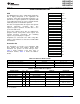
Special Function Registers
Most interrupt and module enable bits are collected into the lowest address space. Special function register bits
not allocated to a functional purpose are not physically present in the device. Simple software access is provided
with this arrangement.
Legend
rw Bit can be read and written.
rw-0, 1 Bit can be read and written. It is Reset or Set by PUC.
rw-(0), (1) Bit can be read and written. It is Reset or Set by POR.
SFR bit is not present in device.
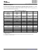
Table 6. Interrupt Enable 1
Address 7 6 5 4 3 2 1 0
00h UTXIE0 URXIE0 ACCVIE NMIIE OFIE WDTIE
rw-0 rw-0 rw-0 rw-0 rw-0 rw-0
WDTIE Watchdog timer interrupt enable. Inactive if watchdog mode is selected. Active if watchdog timer is configured in interval
timer mode.
OFIE Oscillator fault interrupt enable
NMIIE (Non)maskable interrupt enable
ACCVIE Flash access violation interrupt enable
URXIE0 USART0: UART and SPI receive interrupt enable
UTXIE0 USART0: UART and SPI transmit interrupt enable
Table 7. Interrupt Enable 2
Address 7 6 5 4 3 2 1 0
01h
Table 8. Interrupt Flag Register 1
Address 7 6 5 4 3 2 1 0
02h UTXIFG0 URXIFG0 NMIIFG RSTIFG PORIFG OFIFG WDTIFG
rw-1 rw-0 rw-0 rw-(0) rw-(1) rw-1 rw-(0)
WDTIFG Set on watchdog timer overflow (in watchdog mode) or security key violation.
Reset on V
CC
power-up or a reset condition at RST/NMI pin in reset mode.
OFIFG Flag set on oscillator fault
RSTIFG External reset interrupt flag. Set on a reset condition at RST/NMI pin in reset mode. Reset on V
CC
power up.
PORIFG Power-on reset interrupt flag. Set on V
CC
power up.
NMIIFG Set via RST/NMI-pin
URXIFG0 USART0: UART and SPI receive interrupt flag
UTXIFG0 USART0: UART and SPI transmit interrupt flag
Table 9. Interrupt Flag Register 2
Address 7 6 5 4 3 2 1 0
03h
10 Submit Documentation Feedback Copyright © 2010–2011, Texas Instruments Incorporated