
Datasheet


MSP430BT5190
SLAS703A –APRIL 2010–REVISED AUGUST 2013
www.ti.com
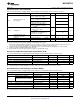
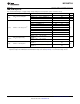
PMM, SVS High Side
over recommended ranges of supply voltage and operating free-air temperature (unless otherwise noted)
PARAMETER TEST CONDITIONS MIN TYP MAX UNIT
SVSHE = 0, DV
CC
= 3.6 V 0 nA
I
(SVSH)
SVS current consumption SVSHE = 1, DV
CC
= 3.6 V, SVSHFP = 0 200 nA
SVSHE = 1, DV
CC
= 3.6 V, SVSHFP = 1 1.5 µA
SVSHE = 1, SVSHRVL = 0 1.57 1.68 1.78
SVSHE = 1, SVSHRVL = 1 1.79 1.88 1.98
V
(SVSH_IT–)
SVS
H
on voltage level
(1)
V
SVSHE = 1, SVSHRVL = 2 1.98 2.08 2.21
SVSHE = 1, SVSHRVL = 3 2.10 2.18 2.31
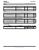
SVSHE = 1, SVSMHRRL = 0 1.62 1.74 1.85
SVSHE = 1, SVSMHRRL = 1 1.88 1.94 2.07
SVSHE = 1, SVSMHRRL = 2 2.07 2.14 2.28
SVSHE = 1, SVSMHRRL = 3 2.20 2.30 2.42
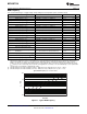
V
(SVSH_IT+)
SVS
H
off voltage level
(1)
V
SVSHE = 1, SVSMHRRL = 4 2.32 2.40 2.55
SVSHE = 1, SVSMHRRL = 5 2.52 2.70 2.88
SVSHE = 1, SVSMHRRL = 6 2.90 3.10 3.23
SVSHE = 1, SVSMHRRL = 7 2.90 3.10 3.23
SVSHE = 1, dV
DVCC
/dt = 10 mV/µs,
2.5
SVSHFP = 1
t
pd(SVSH)
SVS
H
propagation delay µs
SVSHE = 1, dV
DVCC
/dt = 1 mV/µs,
20
SVSHFP = 0
SVSHE = 0 → 1, dV
DVCC
/dt = 10 mV/µs,
12.5
SVSHFP = 1
t
(SVSH)
SVS
H
on or off delay time µs
SVSHE = 0 → 1, dV
DVCC
/dt = 1 mV/µs,
100
SVSHFP = 0
dV
DVCC
/dt DV
CC
rise time 0 1000 V/s
(1) The SVS
H
settings available depend on the VCORE (PMMCOREVx) setting. See the Power Management Module and Supply Voltage
Supervisor chapter in the MSP430x5xx and MSP430x6xx Family User's Guide (SLAU208) on recommended settings and use.
54 Submit Documentation Feedback Copyright © 2010–2013, Texas Instruments Incorporated
Product Folder Links: MSP430BT5190