
Datasheet


MSP430BT5190
SLAS703A –APRIL 2010–REVISED AUGUST 2013
www.ti.com
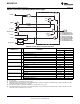
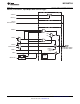
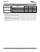
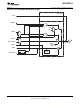
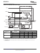
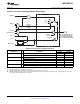
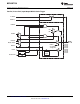
Table 47. Port P4 (P4.0 to P4.7) Pin Functions
CONTROL BITS/SIGNALS
PIN NAME (P4.x) x FUNCTION
P4DIR.x P4SEL.x
P4.0/TB0.0 0 4.0 (I/O) I: 0; O: 1 0
TB0.CCI0A and TB0.CCI0B 0 1
TB0.0
(1)
1 1
P4.1/TB0.1 1 4.1 (I/O) I: 0; O: 1 0
TB0.CCI1A and TB0.CCI1B 0 1
TB0.1
(1)
1 1
P4.2/TB0.2 2 4.2 (I/O) I: 0; O: 1 0
TB0.CCI2A and TB0.CCI2B 0 1
TB0.2
(1)
1 1
P4.3/TB0.3 3 4.3 (I/O) I: 0; O: 1 0
TB0.CCI3A and TB0.CCI3B 0 1
TB0.3
(1)
1 1
P4.4/TB0.5 4 4.4 (I/O) I: 0; O: 1 0
TB0.CCI4A and TB0.CCI4B 0 1
TB0.4
(1)
1 1
P4.5/TB0.5 5 4.5 (I/O) I: 0; O: 1 0
TB0.CCI5A and TB0.CCI5B 0 1
TB0.5
(1)
1 1
P4.6/TB0.6 6 4.6 (I/O) I: 0; O: 1 0
TB0.CCI6A and TB0.CCI6B 0 1
TB0.6
(1)
1 1
P4.7/TB0CLK/SMCLK 7 4.7 (I/O) I: 0; O: 1 0
TB0CLK 0 1
SMCLK 1 1
(1) Setting TBOUTH causes all Timer_B configured outputs to be set to high impedance.
74 Submit Documentation Feedback Copyright © 2010–2013, Texas Instruments Incorporated
Product Folder Links: MSP430BT5190