
Datasheet


MSP430C11x1, MSP430F11x1A
MIXED SIGNAL MICROCONTROLLER
SLAS241I − SEPTEMBER 1999 − REVISED DECEMBER 2008
31
POST OFFICE BOX 655303 • DALLAS, TEXAS 75265
APPLICATION INFORMATION
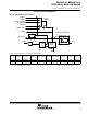
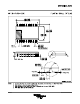
Port P2, unbonded bits P2.6 and P2.7
EN
D
0
1
0
1
Interrupt
Edge
Select
EN
Set
Q
P2IE.x
P2IFG.x
P2IRQ.x
Interrupt
Flag
P2IES.x
P2SEL.x
Module X IN
P2IN.x
P2OUT.x
Module X OUT
Direction Control
From Module
P2DIR.x
P2SEL.x
Bus Keeper
0
1
0: Input
1: Output
Node Is Reset With PUC
PUC
NOTE: x = Bit/identifier, 6 to 7 for port P2 without external pins
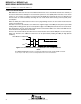
P2Sel.x
P2DIR.x
Direction
control from
module
P2OUT.x Module X OUT P2IN.x Module X IN P2IE.x P2IFG.x P2IES.x
P2Sel.6 P2DIR.6 P2DIR.6 P2OUT.6 V
SS
P2IN.6 unused P2IE.6 P2IFG.6 P2IES.6
P2Sel.7 P2DIR.7 P2DIR.7 P2OUT.7 V
SS
P2IN.7 unused P2IE.7 P2IFG.7 P2IES.7
NOTE 1: Unbonded bits 6 and 7 of port P2 can be used as software interrupt flags. The interrupt flags can only be influenced by software. They
work then as a software interrupt.