MSP430F6638, MSP430F6637, MSP430F6636 MSP430F6635, MSP430F6634, MSP430F6633 MSP430F6632, MSP430F6631, MSP430F6630 www.ti.com SLAS566D – JUNE 2010 – REVISED AUGUST 2013 Mixed Signal Microcontroller Check for Samples: MSP430F6638, MSP430F6637, MSP430F6636, MSP430F6635, MSP430F6634, MSP430F6633, MSP430F6632, MSP430F6631, MSP430F6630 FEATURES 1 • • 23 • • • • Low Supply Voltage Range: 1.8 V to 3.6 V Ultralow-Power Consumption – Active Mode (AM): All System Clocks Active: 270 µA/MHz at 8 MHz, 3.
MSP430F6638, MSP430F6637, MSP430F6636 MSP430F6635, MSP430F6634, MSP430F6633 MSP430F6632, MSP430F6631, MSP430F6630 SLAS566D – JUNE 2010 – REVISED AUGUST 2013 www.ti.com APPLICATIONS • • • • • • Analog and Digital Sensor Systems Digital Motor Control Remote Controls Thermostats Digital Timers Hand-Held Meters DESCRIPTION The Texas Instruments MSP430™ family of ultralow-power microcontrollers consists of several devices featuring different sets of peripherals targeted for various applications.
MSP430F6638, MSP430F6637, MSP430F6636 MSP430F6635, MSP430F6634, MSP430F6633 MSP430F6632, MSP430F6631, MSP430F6630 www.ti.com SLAS566D – JUNE 2010 – REVISED AUGUST 2013 Functional Block Diagram, MSP430F6638, MSP430F6637, MSP430F6636 XIN XOUT DVCC DVSS AVCC AVSS RST/NMI P1.x XT2IN XT2OUT Unified Clock System 16KB RAM ACLK SMCLK 256KB 192KB 128KB Flash MCLK Power Management SYS Watchdog +2KB RAM USB Buffer +8B Backup RAM LDO SVM/SVS Brownout P2 Port Mapping Controller PA P2.x P3.x PB P4.
MSP430F6638, MSP430F6637, MSP430F6636 MSP430F6635, MSP430F6634, MSP430F6633 MSP430F6632, MSP430F6631, MSP430F6630 SLAS566D – JUNE 2010 – REVISED AUGUST 2013 www.ti.com Functional Block Diagram, MSP430F6632, MSP430F6631, MSP430F6630 XIN XOUT DVCC DVSS AVCC AVSS RST/NMI P1.x XT2IN XT2OUT Unified Clock System MCLK ACLK SMCLK 256KB 192KB 128KB Flash 16KB RAM Power Management +2KB RAM USB Buffer +8B Backup RAM SYS Watchdog LDO SVM/SVS Brownout P2 Port Mapping Controller PA P2.x P3.x PB P4.
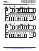
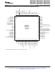
MSP430F6638, MSP430F6637, MSP430F6636 MSP430F6635, MSP430F6634, MSP430F6633 MSP430F6632, MSP430F6631, MSP430F6630 www.ti.com SLAS566D – JUNE 2010 – REVISED AUGUST 2013 1 2 3 4 5 6 7 8 9 10 11 12 13 14 15 16 17 18 19 20 21 22 23 24 25 75 74 73 72 71 70 69 68 67 66 65 64 63 62 61 60 59 58 57 56 55 54 53 52 51 MSP430F6638 MSP430F6637 MSP430F6636 PZ PACKAGE (TOP VIEW) P9.7/S0 P9.6/S1 P9.5/S2 P9.4/S3 P9.3/S4 P9.2/S5 P9.1/S6 P9.0/S7 P8.7/S8 P8.6/UCB1SOMI/UCB1SCL/S9 P8.5/UCB1SIMO/UCB1SDA/S10 DVCC2 DVSS2 P8.
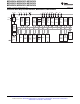
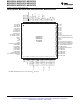
MSP430F6638, MSP430F6637, MSP430F6636 MSP430F6635, MSP430F6634, MSP430F6633 MSP430F6632, MSP430F6631, MSP430F6630 SLAS566D – JUNE 2010 – REVISED AUGUST 2013 www.ti.com 1 2 3 4 5 6 7 8 9 10 11 12 13 14 15 16 17 18 19 20 21 22 23 24 25 75 74 73 72 71 70 69 68 67 66 65 64 63 62 61 60 59 58 57 56 55 54 53 52 51 MSP430F6635 MSP430F6634 MSP430F6633 PZ PACKAGE (TOP VIEW) P9.7/S0 P9.6/S1 P9.5/S2 P9.4/S3 P9.3/S4 P9.2/S5 P9.1/S6 P9.0/S7 P8.7/S8 P8.6/UCB1SOMI/UCB1SCL/S9 P8.5/UCB1SIMO/UCB1SDA/S10 DVCC2 DVSS2 P8.
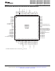
MSP430F6638, MSP430F6637, MSP430F6636 MSP430F6635, MSP430F6634, MSP430F6633 MSP430F6632, MSP430F6631, MSP430F6630 www.ti.com SLAS566D – JUNE 2010 – REVISED AUGUST 2013 1 2 3 4 5 6 7 8 9 10 11 12 13 14 15 16 17 18 19 20 21 22 23 24 25 75 74 73 72 71 70 69 68 67 66 65 64 63 62 61 60 59 58 57 56 55 54 53 52 51 MSP430F6632 MSP430F6631 MSP430F6630 PZ PACKAGE (TOP VIEW) P9.7/S0 P9.6/S1 P9.5/S2 P9.4/S3 P9.3/S4 P9.2/S5 P9.1/S6 P9.0/S7 P8.7/S8 P8.6/UCB1SOMI/UCB1SCL/S9 P8.5/UCB1SIMO/UCB1SDA/S10 DVCC2 DVSS2 P8.
MSP430F6638, MSP430F6637, MSP430F6636 MSP430F6635, MSP430F6634, MSP430F6633 MSP430F6632, MSP430F6631, MSP430F6630 SLAS566D – JUNE 2010 – REVISED AUGUST 2013 www.ti.
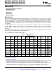
MSP430F6638, MSP430F6637, MSP430F6636 MSP430F6635, MSP430F6634, MSP430F6633 MSP430F6632, MSP430F6631, MSP430F6630 www.ti.com SLAS566D – JUNE 2010 – REVISED AUGUST 2013 Table 2. Terminal Functions TERMINAL NAME I/O (1) NO. DESCRIPTION PZ ZQW P6.4/CB4/A4 1 A1 I/O General-purpose digital I/O Comparator_B input CB4 Analog input A4 – ADC(not available on F6632, F6631, F6630 devices) P6.
MSP430F6638, MSP430F6637, MSP430F6636 MSP430F6635, MSP430F6634, MSP430F6633 MSP430F6632, MSP430F6631, MSP430F6630 SLAS566D – JUNE 2010 – REVISED AUGUST 2013 www.ti.com Table 2. Terminal Functions (continued) TERMINAL NAME I/O (1) NO. DESCRIPTION PZ ZQW P5.6/ADC12CLK/DMAE0 16 H1 I/O General-purpose digital I/O Conversion clock output ADC (not available on F6632, F6631, F6630 devices) DMA external trigger input P2.
MSP430F6638, MSP430F6637, MSP430F6636 MSP430F6635, MSP430F6634, MSP430F6633 MSP430F6632, MSP430F6631, MSP430F6630 www.ti.com SLAS566D – JUNE 2010 – REVISED AUGUST 2013 Table 2. Terminal Functions (continued) TERMINAL NAME P1.0/TA0CLK/ACLK/S39 P1.1/TA0.0/S38 I/O (1) NO.
MSP430F6638, MSP430F6637, MSP430F6636 MSP430F6635, MSP430F6634, MSP430F6633 MSP430F6632, MSP430F6631, MSP430F6630 SLAS566D – JUNE 2010 – REVISED AUGUST 2013 www.ti.com Table 2. Terminal Functions (continued) TERMINAL NAME I/O (1) NO. DESCRIPTION PZ ZQW P3.5/TA2.0/S26 47 M9 I/O General-purpose digital I/O with port interrupt Timer TA2 capture CCR0: CCI0A/CCI0B input, compare: Out0 output LCD segment output S26 P3.6/TA2.
MSP430F6638, MSP430F6637, MSP430F6636 MSP430F6635, MSP430F6634, MSP430F6633 MSP430F6632, MSP430F6631, MSP430F6630 www.ti.com SLAS566D – JUNE 2010 – REVISED AUGUST 2013 Table 2. Terminal Functions (continued) TERMINAL NAME I/O (1) NO. DESCRIPTION PZ ZQW P8.3/UCA1RXD/UCA1SOMI/S12 61 H12 I/O General-purpose digital I/O USCI_A1 UART receive data; USCI_A1 SPI slave out/master in LCD segment output S12 P8.
MSP430F6638, MSP430F6637, MSP430F6636 MSP430F6635, MSP430F6634, MSP430F6633 MSP430F6632, MSP430F6631, MSP430F6630 SLAS566D – JUNE 2010 – REVISED AUGUST 2013 www.ti.com Table 2. Terminal Functions (continued) TERMINAL NAME I/O (1) NO. DESCRIPTION PZ ZQW AVSS3 83 A8 P7.2/XT2IN 84 B8 I/O General-purpose digital I/O Input terminal for crystal oscillator XT2 P7.
MSP430F6638, MSP430F6637, MSP430F6636 MSP430F6635, MSP430F6634, MSP430F6633 MSP430F6632, MSP430F6631, MSP430F6630 www.ti.com SLAS566D – JUNE 2010 – REVISED AUGUST 2013 Table 2. Terminal Functions (continued) TERMINAL NAME Reserved NO. PZ ZQW N/A E5, E6, E8, F4, F5, F8, G5, G8, H5, H8, H9 Copyright © 2010–2013, Texas Instruments Incorporated I/O (1) DESCRIPTION Reserved. It is recommended to connect to ground (DVSS, AVSS).
MSP430F6638, MSP430F6637, MSP430F6636 MSP430F6635, MSP430F6634, MSP430F6633 MSP430F6632, MSP430F6631, MSP430F6630 SLAS566D – JUNE 2010 – REVISED AUGUST 2013 www.ti.com Development Tools Support All MSP430™ microcontrollers are supported by a wide variety of software and hardware development tools. Tools are available from TI and various third parties. See them all at www.ti.com/msp430tools.
MSP430F6638, MSP430F6637, MSP430F6636 MSP430F6635, MSP430F6634, MSP430F6633 MSP430F6632, MSP430F6631, MSP430F6630 www.ti.com SLAS566D – JUNE 2010 – REVISED AUGUST 2013 TI-RTOS TI-RTOS is a complete real-time operating system for the MSP430 microcontrollers. It combines a real-time multitasking kernel SYS/BIOS with additional middleware components. TI-RTOS is available free of charge and provided with full source code.
MSP430F6638, MSP430F6637, MSP430F6636 MSP430F6635, MSP430F6634, MSP430F6633 MSP430F6632, MSP430F6631, MSP430F6630 SLAS566D – JUNE 2010 – REVISED AUGUST 2013 www.ti.com TI device nomenclature also includes a suffix with the device family name. This suffix indicates the package type (for example, PZP) and temperature range (for example, T). Figure 1 provides a legend for reading the complete device name for any family member.
MSP430F6638, MSP430F6637, MSP430F6636 MSP430F6635, MSP430F6634, MSP430F6633 MSP430F6632, MSP430F6631, MSP430F6630 www.ti.com SLAS566D – JUNE 2010 – REVISED AUGUST 2013 Short-Form Description CPU The MSP430 CPU has a 16-bit RISC architecture that is highly transparent to the application. All operations, other than program-flow instructions, are performed as register operations in conjunction with seven addressing modes for source operand and four addressing modes for destination operand.
MSP430F6638, MSP430F6637, MSP430F6636 MSP430F6635, MSP430F6634, MSP430F6633 MSP430F6632, MSP430F6631, MSP430F6630 SLAS566D – JUNE 2010 – REVISED AUGUST 2013 www.ti.com Operating Modes The MSP430 has one active mode and seven software selectable low-power modes of operation. An interrupt event can wake up the device from any of the low-power modes, service the request, and restore back to the low-power mode on return from the interrupt program.
MSP430F6638, MSP430F6637, MSP430F6636 MSP430F6635, MSP430F6634, MSP430F6633 MSP430F6632, MSP430F6631, MSP430F6630 www.ti.com SLAS566D – JUNE 2010 – REVISED AUGUST 2013 Interrupt Vector Addresses The interrupt vectors and the power-up start address are located in the address range 0FFFFh to 0FF80h. The vector contains the 16-bit address of the appropriate interrupt-handler instruction sequence. Table 5.
MSP430F6638, MSP430F6637, MSP430F6636 MSP430F6635, MSP430F6634, MSP430F6633 MSP430F6632, MSP430F6631, MSP430F6630 SLAS566D – JUNE 2010 – REVISED AUGUST 2013 www.ti.com Table 5.
MSP430F6638, MSP430F6637, MSP430F6636 MSP430F6635, MSP430F6634, MSP430F6633 MSP430F6632, MSP430F6631, MSP430F6630 www.ti.com SLAS566D – JUNE 2010 – REVISED AUGUST 2013 Bootstrap Loader (BSL) The BSL enables users to program the flash memory or RAM using various serial interfaces. Access to the device memory via the BSL is protected by an user-defined password. For complete description of the features of the BSL and its implementation, see MSP430 Programming Via the Bootstrap Loader (BSL) (SLAU319).
MSP430F6638, MSP430F6637, MSP430F6636 MSP430F6635, MSP430F6634, MSP430F6633 MSP430F6632, MSP430F6631, MSP430F6630 SLAS566D – JUNE 2010 – REVISED AUGUST 2013 www.ti.com Table 9. JTAG Pin Requirements and Functions DEVICE SIGNAL DIRECTION FUNCTION PJ.3/TCK IN JTAG clock input PJ.2/TMS IN JTAG state control PJ.1/TDI/TCLK IN JTAG data input, TCLK input PJ.
MSP430F6638, MSP430F6637, MSP430F6636 MSP430F6635, MSP430F6634, MSP430F6633 MSP430F6632, MSP430F6631, MSP430F6630 www.ti.com SLAS566D – JUNE 2010 – REVISED AUGUST 2013 Peripherals Peripherals are connected to the CPU through data, address, and control buses and can be handled using all instructions. For complete module descriptions, see the MSP430x5xx and MSP430x6xx Family User's Guide (SLAU208).
MSP430F6638, MSP430F6637, MSP430F6636 MSP430F6635, MSP430F6634, MSP430F6633 MSP430F6632, MSP430F6631, MSP430F6630 SLAS566D – JUNE 2010 – REVISED AUGUST 2013 www.ti.com Table 11. Port Mapping, Mnemonics and Functions (continued) VALUE PxMAPy MNEMONIC 19 Reserved 20-30 (1) OUTPUT PIN FUNCTION Reserved for test purposes. Do not use this setting.
MSP430F6638, MSP430F6637, MSP430F6636 MSP430F6635, MSP430F6634, MSP430F6633 MSP430F6632, MSP430F6631, MSP430F6630 www.ti.com SLAS566D – JUNE 2010 – REVISED AUGUST 2013 Hardware Multiplier (MPY) (Link to User's Guide) The multiplication operation is supported by a dedicated peripheral module. The module performs operations with 32-bit, 24-bit, 16-bit, and 8-bit operands. The module is capable of supporting signed and unsigned multiplication as well as signed and unsigned multiply and accumulate operations.
MSP430F6638, MSP430F6637, MSP430F6636 MSP430F6635, MSP430F6634, MSP430F6633 MSP430F6632, MSP430F6631, MSP430F6630 SLAS566D – JUNE 2010 – REVISED AUGUST 2013 www.ti.com Table 13.
MSP430F6638, MSP430F6637, MSP430F6636 MSP430F6635, MSP430F6634, MSP430F6633 MSP430F6632, MSP430F6631, MSP430F6630 www.ti.com SLAS566D – JUNE 2010 – REVISED AUGUST 2013 DMA Controller (Link to User's Guide) The DMA controller allows movement of data from one memory address to another without CPU intervention. For example, the DMA controller can be used to move data from the ADC12_A conversion memory to RAM. Using the DMA controller can increase the throughput of peripheral modules.
MSP430F6638, MSP430F6637, MSP430F6636 MSP430F6635, MSP430F6634, MSP430F6633 MSP430F6632, MSP430F6631, MSP430F6630 SLAS566D – JUNE 2010 – REVISED AUGUST 2013 www.ti.com Universal Serial Communication Interface (USCI) (Links to User's Guide: UART Mode, SPI Mode, I2C Mode) The USCI modules are used for serial data communication.
MSP430F6638, MSP430F6637, MSP430F6636 MSP430F6635, MSP430F6634, MSP430F6633 MSP430F6632, MSP430F6631, MSP430F6630 www.ti.com SLAS566D – JUNE 2010 – REVISED AUGUST 2013 Timer TA1 (Link to User's Guide) Timer TA1 is a 16-bit timer/counter (Timer_A type) with three capture/compare registers. It supports multiple capture/compares, PWM outputs, and interval timing. It also has extensive interrupt capabilities.
MSP430F6638, MSP430F6637, MSP430F6636 MSP430F6635, MSP430F6634, MSP430F6633 MSP430F6632, MSP430F6631, MSP430F6630 SLAS566D – JUNE 2010 – REVISED AUGUST 2013 www.ti.com Timer TA2 (Link to User's Guide) Timer TA2 is a 16-bit timer/counter (Timer_A type) with three capture/compare registers. It supports multiple capture/compares, PWM outputs, and interval timing. It also has extensive interrupt capabilities.
MSP430F6638, MSP430F6637, MSP430F6636 MSP430F6635, MSP430F6634, MSP430F6633 MSP430F6632, MSP430F6631, MSP430F6630 www.ti.com SLAS566D – JUNE 2010 – REVISED AUGUST 2013 Timer TB0 (Link to User's Guide) Timer TB0 is a 16-bit timer/counter (Timer_B type) with seven capture/compare registers. It supports multiple capture/compares, PWM outputs, and interval timing. It also has extensive interrupt capabilities.
MSP430F6638, MSP430F6637, MSP430F6636 MSP430F6635, MSP430F6634, MSP430F6633 MSP430F6632, MSP430F6631, MSP430F6630 SLAS566D – JUNE 2010 – REVISED AUGUST 2013 www.ti.com Comparator_B (Link to User's Guide) The primary function of the Comparator_B module is to support precision slope analog-to-digital conversions, battery voltage supervision, and monitoring of external analog signals. ADC12_A (Link to User's Guide) The ADC12_A module supports fast 12-bit analog-to-digital conversions.
MSP430F6638, MSP430F6637, MSP430F6636 MSP430F6635, MSP430F6634, MSP430F6633 MSP430F6632, MSP430F6631, MSP430F6630 www.ti.com SLAS566D – JUNE 2010 – REVISED AUGUST 2013 Peripheral File Map Table 19.
MSP430F6638, MSP430F6637, MSP430F6636 MSP430F6635, MSP430F6634, MSP430F6633 MSP430F6632, MSP430F6631, MSP430F6630 SLAS566D – JUNE 2010 – REVISED AUGUST 2013 www.ti.com Table 20. Special Function Registers (Base Address: 0100h) REGISTER DESCRIPTION REGISTER OFFSET SFR interrupt enable SFRIE1 00h SFR interrupt flag SFRIFG1 02h SFR reset pin control SFRRPCR 04h Table 21.
MSP430F6638, MSP430F6637, MSP430F6636 MSP430F6635, MSP430F6634, MSP430F6633 MSP430F6632, MSP430F6631, MSP430F6630 www.ti.com SLAS566D – JUNE 2010 – REVISED AUGUST 2013 Table 27.
MSP430F6638, MSP430F6637, MSP430F6636 MSP430F6635, MSP430F6634, MSP430F6633 MSP430F6632, MSP430F6631, MSP430F6630 SLAS566D – JUNE 2010 – REVISED AUGUST 2013 www.ti.com Table 30. Port P1/P2 Registers (Base Address: 0200h) (continued) REGISTER DESCRIPTION REGISTER OFFSET Port P2 selection P2SEL 0Bh Port P2 interrupt vector word P2IV 1Eh Port P2 interrupt edge select P2IES 19h Port P2 interrupt enable P2IE 1Bh Port P2 interrupt flag P2IFG 1Dh Table 31.
MSP430F6638, MSP430F6637, MSP430F6636 MSP430F6635, MSP430F6634, MSP430F6633 MSP430F6632, MSP430F6631, MSP430F6630 www.ti.com SLAS566D – JUNE 2010 – REVISED AUGUST 2013 Table 33.
MSP430F6638, MSP430F6637, MSP430F6636 MSP430F6635, MSP430F6634, MSP430F6633 MSP430F6632, MSP430F6631, MSP430F6630 SLAS566D – JUNE 2010 – REVISED AUGUST 2013 www.ti.com Table 37.
MSP430F6638, MSP430F6637, MSP430F6636 MSP430F6635, MSP430F6634, MSP430F6633 MSP430F6632, MSP430F6631, MSP430F6630 www.ti.com SLAS566D – JUNE 2010 – REVISED AUGUST 2013 Table 40. Battery Backup Registers (Base Address: 0480h) REGISTER DESCRIPTION REGISTER OFFSET Battery Backup Memory 0 BAKMEM0 00h Battery Backup Memory 1 BAKMEM1 02h Battery Backup Memory 2 BAKMEM2 04h Battery Backup Memory 3 BAKMEM3 06h Battery Backup Control BAKCTL 1Ch Battery Charger Control BAKCHCTL 1Eh Table 41.
MSP430F6638, MSP430F6637, MSP430F6636 MSP430F6635, MSP430F6634, MSP430F6633 MSP430F6632, MSP430F6631, MSP430F6630 SLAS566D – JUNE 2010 – REVISED AUGUST 2013 www.ti.com Table 42.
MSP430F6638, MSP430F6637, MSP430F6636 MSP430F6635, MSP430F6634, MSP430F6633 MSP430F6632, MSP430F6631, MSP430F6630 www.ti.com SLAS566D – JUNE 2010 – REVISED AUGUST 2013 Table 43.
MSP430F6638, MSP430F6637, MSP430F6636 MSP430F6635, MSP430F6634, MSP430F6633 MSP430F6632, MSP430F6631, MSP430F6630 SLAS566D – JUNE 2010 – REVISED AUGUST 2013 www.ti.com Table 46.
MSP430F6638, MSP430F6637, MSP430F6636 MSP430F6635, MSP430F6634, MSP430F6633 MSP430F6632, MSP430F6631, MSP430F6630 www.ti.com SLAS566D – JUNE 2010 – REVISED AUGUST 2013 Table 48.
MSP430F6638, MSP430F6637, MSP430F6636 MSP430F6635, MSP430F6634, MSP430F6633 MSP430F6632, MSP430F6631, MSP430F6630 SLAS566D – JUNE 2010 – REVISED AUGUST 2013 www.ti.com Table 51.
MSP430F6638, MSP430F6637, MSP430F6636 MSP430F6635, MSP430F6634, MSP430F6633 MSP430F6632, MSP430F6631, MSP430F6630 www.ti.com SLAS566D – JUNE 2010 – REVISED AUGUST 2013 Table 53.
MSP430F6638, MSP430F6637, MSP430F6636 MSP430F6635, MSP430F6634, MSP430F6633 MSP430F6632, MSP430F6631, MSP430F6630 SLAS566D – JUNE 2010 – REVISED AUGUST 2013 www.ti.com Absolute Maximum Ratings (1) over operating free-air temperature range (unless otherwise noted) Voltage applied at VCC to VSS –0.3 V to 4.1 V Voltage applied to any pin (excluding VCORE, VBUS, V18) (2) –0.3 V to VCC + 0.
MSP430F6638, MSP430F6637, MSP430F6636 MSP430F6635, MSP430F6634, MSP430F6633 MSP430F6632, MSP430F6631, MSP430F6630 www.ti.
MSP430F6638, MSP430F6637, MSP430F6636 MSP430F6635, MSP430F6634, MSP430F6633 MSP430F6632, MSP430F6631, MSP430F6630 SLAS566D – JUNE 2010 – REVISED AUGUST 2013 www.ti.com Electrical Characteristics Active Mode Supply Current Into VCC Excluding External Current over recommended operating free-air temperature (unless otherwise noted) (1) (2) (3) FREQUENCY (fDCO = fMCLK = fSMCLK) PARAMETER EXECUTION MEMORY VCC PMMCOREVx 1 MHz TYP IAM, IAM, (1) (2) (3) 50 Flash RAM Flash RAM 3V 3V 8 MHz MAX 0.
MSP430F6638, MSP430F6637, MSP430F6636 MSP430F6635, MSP430F6634, MSP430F6633 MSP430F6632, MSP430F6631, MSP430F6630 www.ti.com SLAS566D – JUNE 2010 – REVISED AUGUST 2013 Low-Power Mode Supply Currents (Into VCC) Excluding External Current over recommended ranges of supply voltage and operating free-air temperature (unless otherwise noted) (1) (2) PARAMETER ILPM0,1MHz Low-power mode 0 (3) (4) ILPM2 Low-power mode 2 (5) (4) VLO,WDT ILPM4 ILPM3.5, RTC,VCC ILPM3.5, RTC,VBAT ILPM3.
MSP430F6638, MSP430F6637, MSP430F6636 MSP430F6635, MSP430F6634, MSP430F6633 MSP430F6632, MSP430F6631, MSP430F6630 SLAS566D – JUNE 2010 – REVISED AUGUST 2013 www.ti.com Low-Power Mode Supply Currents (Into VCC) Excluding External Current (continued) over recommended ranges of supply voltage and operating free-air temperature (unless otherwise noted)(1)(2) PARAMETER VCC Low-power mode 4.5 (LPM4.5) (12) ILPM4.5 PMMCOREVx -40°C TYP 3V MAX 0.2 25°C TYP 60°C MAX 0.3 TYP 0.6 85°C MAX TYP 0.
MSP430F6638, MSP430F6637, MSP430F6636 MSP430F6635, MSP430F6634, MSP430F6633 MSP430F6632, MSP430F6631, MSP430F6630 www.ti.
MSP430F6638, MSP430F6637, MSP430F6636 MSP430F6635, MSP430F6634, MSP430F6633 MSP430F6632, MSP430F6631, MSP430F6630 SLAS566D – JUNE 2010 – REVISED AUGUST 2013 www.ti.com Outputs – General Purpose I/O (Reduced Drive Strength) over recommended ranges of supply voltage and operating free-air temperature (unless otherwise noted) (1) PARAMETER TEST CONDITIONS I(OHmax) = –1 mA VOH High-level output voltage 1.
MSP430F6638, MSP430F6637, MSP430F6636 MSP430F6635, MSP430F6634, MSP430F6633 MSP430F6632, MSP430F6631, MSP430F6630 www.ti.com SLAS566D – JUNE 2010 – REVISED AUGUST 2013 Typical Characteristics – Outputs, Reduced Drive Strength (PxDS.y = 0) over recommended ranges of supply voltage and operating free-air temperature (unless otherwise noted) TYPICAL LOW-LEVEL OUTPUT CURRENT vs LOW-LEVEL OUTPUT VOLTAGE TYPICAL LOW-LEVEL OUTPUT CURRENT vs LOW-LEVEL OUTPUT VOLTAGE 8.0 VCC = 3.0 V P3.
MSP430F6638, MSP430F6637, MSP430F6636 MSP430F6635, MSP430F6634, MSP430F6633 MSP430F6632, MSP430F6631, MSP430F6630 SLAS566D – JUNE 2010 – REVISED AUGUST 2013 www.ti.com Typical Characteristics – Outputs, Full Drive Strength (PxDS.y = 1) over recommended ranges of supply voltage and operating free-air temperature (unless otherwise noted) TYPICAL LOW-LEVEL OUTPUT CURRENT vs LOW-LEVEL OUTPUT VOLTAGE TYPICAL LOW-LEVEL OUTPUT CURRENT vs LOW-LEVEL OUTPUT VOLTAGE 55.0 VCC = 3.0 V P3.
MSP430F6638, MSP430F6637, MSP430F6636 MSP430F6635, MSP430F6634, MSP430F6633 MSP430F6632, MSP430F6631, MSP430F6630 www.ti.
MSP430F6638, MSP430F6637, MSP430F6636 MSP430F6635, MSP430F6634, MSP430F6633 MSP430F6632, MSP430F6631, MSP430F6630 SLAS566D – JUNE 2010 – REVISED AUGUST 2013 www.ti.
MSP430F6638, MSP430F6637, MSP430F6636 MSP430F6635, MSP430F6634, MSP430F6633 MSP430F6632, MSP430F6631, MSP430F6630 www.ti.com SLAS566D – JUNE 2010 – REVISED AUGUST 2013 Internal Very-Low-Power Low-Frequency Oscillator (VLO) over recommended ranges of supply voltage and operating free-air temperature (unless otherwise noted) PARAMETER TEST CONDITIONS VCC fVLO VLO frequency Measured at ACLK 1.8 V to 3.6 V dfVLO/dT VLO frequency temperature drift Measured at ACLK (1) 1.8 V to 3.
MSP430F6638, MSP430F6637, MSP430F6636 MSP430F6635, MSP430F6634, MSP430F6633 MSP430F6632, MSP430F6631, MSP430F6630 SLAS566D – JUNE 2010 – REVISED AUGUST 2013 www.ti.com DCO Frequency over recommended ranges of supply voltage and operating free-air temperature (unless otherwise noted) PARAMETER TEST CONDITIONS MIN TYP MAX UNIT fDCO(0,0) DCO frequency (0, 0) DCORSELx = 0, DCOx = 0, MODx = 0 0.07 0.20 MHz fDCO(0,31) DCO frequency (0, 31) DCORSELx = 0, DCOx = 31, MODx = 0 0.70 1.
MSP430F6638, MSP430F6637, MSP430F6636 MSP430F6635, MSP430F6634, MSP430F6633 MSP430F6632, MSP430F6631, MSP430F6630 www.ti.
MSP430F6638, MSP430F6637, MSP430F6636 MSP430F6635, MSP430F6634, MSP430F6633 MSP430F6632, MSP430F6631, MSP430F6630 SLAS566D – JUNE 2010 – REVISED AUGUST 2013 www.ti.com PMM, SVS High Side (continued) over recommended ranges of supply voltage and operating free-air temperature (unless otherwise noted) PARAMETER TEST CONDITIONS tpd(SVSH) SVSH propagation delay t(SVSH) SVSH on/off delay time dVDVCC/dt DVCC rise time MIN TYP SVSHE = 1, dVDVCC/dt = 10 mV/µs, SVSHFP = 1 2.
MSP430F6638, MSP430F6637, MSP430F6636 MSP430F6635, MSP430F6634, MSP430F6633 MSP430F6632, MSP430F6631, MSP430F6630 www.ti.com SLAS566D – JUNE 2010 – REVISED AUGUST 2013 PMM, SVM Low Side (continued) over recommended ranges of supply voltage and operating free-air temperature (unless otherwise noted) PARAMETER tpd(SVML) SVML propagation delay t(SVML) SVML on/off delay time TEST CONDITIONS MIN TYP SVMLE = 1, dVCORE/dt = 10 mV/µs, SVMLFP = 1 2.
MSP430F6638, MSP430F6637, MSP430F6636 MSP430F6635, MSP430F6634, MSP430F6633 MSP430F6632, MSP430F6631, MSP430F6630 SLAS566D – JUNE 2010 – REVISED AUGUST 2013 www.ti.com Battery Backup over operating free-air temperature range (unless otherwise noted) PARAMETER TEST CONDITIONS VBAT = 1.7 V, DVCC not connected, RTC running Current into VBAT terminal in VBAT = 2.2 V, case no primary battery is DVCC not connected, connected.
MSP430F6638, MSP430F6637, MSP430F6636 MSP430F6635, MSP430F6634, MSP430F6633 MSP430F6632, MSP430F6631, MSP430F6630 www.ti.
MSP430F6638, MSP430F6637, MSP430F6636 MSP430F6635, MSP430F6634, MSP430F6633 MSP430F6632, MSP430F6631, MSP430F6630 SLAS566D – JUNE 2010 – REVISED AUGUST 2013 www.ti.com 1/fUCxCLK CKPL = 0 UCLK CKPL = 1 tLO/HI tLO/HI tHD,MI tSU,MI SOMI tHD,MO tVALID,MO SIMO Figure 13.
MSP430F6638, MSP430F6637, MSP430F6636 MSP430F6635, MSP430F6634, MSP430F6633 MSP430F6632, MSP430F6631, MSP430F6630 www.ti.
MSP430F6638, MSP430F6637, MSP430F6636 MSP430F6635, MSP430F6634, MSP430F6633 MSP430F6632, MSP430F6631, MSP430F6630 SLAS566D – JUNE 2010 – REVISED AUGUST 2013 www.ti.com tSTE,LEAD tSTE,LAG STE 1/fUCxCLK CKPL = 0 UCLK CKPL = 1 tLO/HI tSU,SI tLO/HI tHD,SI SIMO tHD,SO tVALID,SO tSTE,ACC tSTE,DIS SOMI Figure 14. SPI Slave Mode, CKPH = 0 tSTE,LAG tSTE,LEAD STE 1/fUCxCLK CKPL = 0 UCLK CKPL = 1 tLO/HI tLO/HI tHD,SI tSU,SI SIMO tSTE,ACC tHD,MO tVALID,SO tSTE,DIS SOMI Figure 15.
MSP430F6638, MSP430F6637, MSP430F6636 MSP430F6635, MSP430F6634, MSP430F6633 MSP430F6632, MSP430F6631, MSP430F6630 www.ti.
MSP430F6638, MSP430F6637, MSP430F6636 MSP430F6635, MSP430F6634, MSP430F6633 MSP430F6632, MSP430F6631, MSP430F6630 SLAS566D – JUNE 2010 – REVISED AUGUST 2013 www.ti.com LCD_B, Recommended Operating Conditions PARAMETER CONDITIONS MIN NOM MAX UNIT Supply voltage range, charge pump enabled, VLCD ≤ 3.6 V LCDCPEN = 1, 0000 < VLCDx ≤ 1111 (charge pump enabled, VLCD ≤ 3.6 V) 2.2 3.6 V Supply voltage range, charge pump enabled, VLCD ≤ 3.
MSP430F6638, MSP430F6637, MSP430F6636 MSP430F6635, MSP430F6634, MSP430F6633 MSP430F6632, MSP430F6631, MSP430F6630 www.ti.com SLAS566D – JUNE 2010 – REVISED AUGUST 2013 LCD_B, Electrical Characteristics over operating free-air temperature range (unless otherwise noted) PARAMETER VLCD LCD voltage TEST CONDITIONS VCC MIN TYP MAX UNIT VLCDx = 0000, VLCDEXT = 0 2.4 V - 3.6 V VCC V LCDCPEN = 1, VLCDx = 0001 2 V - 3.6 V 2.60 V LCDCPEN = 1, VLCDx = 0010 2 V - 3.6 V 2.
MSP430F6638, MSP430F6637, MSP430F6636 MSP430F6635, MSP430F6634, MSP430F6633 MSP430F6632, MSP430F6631, MSP430F6630 SLAS566D – JUNE 2010 – REVISED AUGUST 2013 www.ti.
MSP430F6638, MSP430F6637, MSP430F6636 MSP430F6635, MSP430F6634, MSP430F6633 MSP430F6632, MSP430F6631, MSP430F6630 www.ti.com SLAS566D – JUNE 2010 – REVISED AUGUST 2013 12-Bit ADC, Linearity Parameters Using AVCC as Reference Voltage (continued) over recommended ranges of supply voltage and operating free-air temperature (unless otherwise noted) PARAMETER TEST CONDITIONS VCC MIN TYP MAX UNIT EO Offset error See (2) 2.2 V, 3 V ±1 ±2 LSB EG Gain error (3) See (2) 2.
MSP430F6638, MSP430F6637, MSP430F6636 MSP430F6635, MSP430F6634, MSP430F6633 MSP430F6632, MSP430F6631, MSP430F6630 SLAS566D – JUNE 2010 – REVISED AUGUST 2013 www.ti.com Typical Temperature Sensor Voltage - mV 1000 950 900 850 800 750 700 650 600 550 500 -40 -30 -20 -10 0 10 20 30 40 50 60 70 80 Ambient Temperature - ˚C Figure 17.
MSP430F6638, MSP430F6637, MSP430F6636 MSP430F6635, MSP430F6634, MSP430F6633 MSP430F6632, MSP430F6631, MSP430F6630 www.ti.com SLAS566D – JUNE 2010 – REVISED AUGUST 2013 REF, Built-In Reference over recommended ranges of supply voltage and operating free-air temperature (unless otherwise noted) (1) PARAMETER TEST CONDITIONS REFVSEL = {2} for 2.
MSP430F6638, MSP430F6637, MSP430F6636 MSP430F6635, MSP430F6634, MSP430F6633 MSP430F6632, MSP430F6631, MSP430F6630 SLAS566D – JUNE 2010 – REVISED AUGUST 2013 www.ti.
MSP430F6638, MSP430F6637, MSP430F6636 MSP430F6635, MSP430F6634, MSP430F6633 MSP430F6632, MSP430F6631, MSP430F6630 www.ti.
MSP430F6638, MSP430F6637, MSP430F6636 MSP430F6635, MSP430F6634, MSP430F6633 MSP430F6632, MSP430F6631, MSP430F6630 SLAS566D – JUNE 2010 – REVISED AUGUST 2013 www.ti.
MSP430F6638, MSP430F6637, MSP430F6636 MSP430F6635, MSP430F6634, MSP430F6633 MSP430F6632, MSP430F6631, MSP430F6630 www.ti.com SLAS566D – JUNE 2010 – REVISED AUGUST 2013 12-Bit DAC, Reference Input Specifications over recommended ranges of supply voltage and operating free-air temperature (unless otherwise noted) PARAMETER TEST CONDITIONS DAC12IR = 0 (1) Reference input voltage range VeREF+ VCC (2) 2.
MSP430F6638, MSP430F6637, MSP430F6636 MSP430F6635, MSP430F6634, MSP430F6633 MSP430F6632, MSP430F6631, MSP430F6630 SLAS566D – JUNE 2010 – REVISED AUGUST 2013 www.ti.com Conversion 1 Conversion 2 Conversion 3 VOUT 90% 90% 10% 10% tSRHL tSRLH Figure 21. Slew Rate Testing 12-Bit DAC, Dynamic Specifications (Continued) over recommended ranges of supply voltage and TA = 25°C (unless otherwise noted) PARAMETER BW–3dB TEST CONDITIONS 3-dB bandwidth, VDC = 1.5 V, VAC = 0.
MSP430F6638, MSP430F6637, MSP430F6636 MSP430F6635, MSP430F6634, MSP430F6633 MSP430F6632, MSP430F6631, MSP430F6630 www.ti.com SLAS566D – JUNE 2010 – REVISED AUGUST 2013 Comparator_B over recommended ranges of supply voltage and operating free-air temperature (unless otherwise noted) PARAMETER VCC TEST CONDITIONS VCC MIN Supply voltage TYP 1.8 MAX 3.6 1.
MSP430F6638, MSP430F6637, MSP430F6636 MSP430F6635, MSP430F6634, MSP430F6633 MSP430F6632, MSP430F6631, MSP430F6630 SLAS566D – JUNE 2010 – REVISED AUGUST 2013 www.ti.com Ports PU.0 and PU.1 over recommended ranges of supply voltage and operating free-air temperature (unless otherwise noted) PARAMETER TEST CONDITIONS VCC VOH High-level output voltage VUSB = 3.3 V ± 10%, IOH = -25 mA VOL Low-level output voltage VUSB = 3.3 V ± 10%, IOL = 25 mA VIH High-level input voltage VUSB = 3.
MSP430F6638, MSP430F6637, MSP430F6636 MSP430F6635, MSP430F6634, MSP430F6633 MSP430F6632, MSP430F6631, MSP430F6630 www.ti.com SLAS566D – JUNE 2010 – REVISED AUGUST 2013 USB-PLL (USB Phase-Locked Loop) over recommended ranges of supply voltage and operating free-air temperature (unless otherwise noted) PARAMETER IPLL Operating supply current fPLL PLL frequency fUPD PLL reference frequency tLOCK PLL lock time tJitter PLL jitter TEST CONDITIONS VCC MIN TYP MAX 7 48 UNIT mA MHz 1.
MSP430F6638, MSP430F6637, MSP430F6636 MSP430F6635, MSP430F6634, MSP430F6633 MSP430F6632, MSP430F6631, MSP430F6630 SLAS566D – JUNE 2010 – REVISED AUGUST 2013 www.ti.com INPUT/OUTPUT SCHEMATICS Port P1, P1.0 to P1.7, Input/Output With Schmitt Trigger Pad Logic S32...S39 LCDS32...LCDS39 P1REN.x P1DIR.x 0 0 Module X OUT 1 0 DVCC 1 P1DS.x 0: Low drive 1: High drive P1SEL.x P1IN.x Bus Keeper EN Module X IN 1 Direction 0: Input 1: Output 1 P1OUT.x DVSS P1.0/TA0CLK/ACLK/S39 P1.1/TA0.0/S38 P1.
MSP430F6638, MSP430F6637, MSP430F6636 MSP430F6635, MSP430F6634, MSP430F6633 MSP430F6632, MSP430F6631, MSP430F6630 www.ti.com SLAS566D – JUNE 2010 – REVISED AUGUST 2013 Table 54. Port P1 (P1.0 to P1.7) Pin Functions PIN NAME (P1.x) x P1.0/TA0CLK/ACLK/ S39 0 P1.1/TA0.0/S38 1 FUNCTION P1.0 (I/O) 2 3 P1.5/TA0.4/S34 P1.6/TA0.1/S33 4 5 6 0 0 1 0 ACLK 1 1 0 S39 X X 1 P1.1 (I/O) I: 0; O: 1 0 0 Timer TA0.CCI0A capture input 0 1 0 Timer TA0.0 output 1 1 0 P1.
MSP430F6638, MSP430F6637, MSP430F6636 MSP430F6635, MSP430F6634, MSP430F6633 MSP430F6632, MSP430F6631, MSP430F6630 SLAS566D – JUNE 2010 – REVISED AUGUST 2013 www.ti.com Port P2, P2.0 to P2.7, Input/Output With Schmitt Trigger Pad Logic to LCD_B from LCD_B P2REN.x P2DIR.x 0 From Port Mapping 1 P2OUT.x 0 From Port Mapping 1 DVSS 0 DVCC 1 1 Direction 0: Input 1: Output P2DS.x 0: Low drive 1: High drive P2SEL.x P2IN.x From Port Mapping P2.0/P2MAP0 P2.1/P2MAP1 P2.2/P2MAP2 P2.3/P2MAP3 P2.
MSP430F6638, MSP430F6637, MSP430F6636 MSP430F6635, MSP430F6634, MSP430F6633 MSP430F6632, MSP430F6631, MSP430F6630 www.ti.com SLAS566D – JUNE 2010 – REVISED AUGUST 2013 Table 55. Port P2 (P2.0 to P2.7) Pin Functions PIN NAME (P2.x) P2.0/P2MAP0 x 0 FUNCTION P2.0 (I/O) Mapped secondary digital function P2.1/P2MAP1 1 P2.1 (I/O) Mapped secondary digital function P2.2/P2MAP2 2 P2.2 (I/O) Mapped secondary digital function P2.3/P2MAP3 3 P2.4/P2MAP4 4 P2.3 (I/O) Mapped secondary digital function P2.
MSP430F6638, MSP430F6637, MSP430F6636 MSP430F6635, MSP430F6634, MSP430F6633 MSP430F6632, MSP430F6631, MSP430F6630 SLAS566D – JUNE 2010 – REVISED AUGUST 2013 www.ti.com Port P3, P3.0 to P3.7, Input/Output With Schmitt Trigger Pad Logic S24...S31 LCDS24...LCDS31 P3REN.x P3DIR.x 0 0 Module X OUT 1 0 DVCC 1 P3DS.x 0: Low drive 1: High drive P3SEL.x P3IN.x Bus Keeper EN Module X IN 1 Direction 0: Input 1: Output 1 P3OUT.x DVSS P3.0/TA1CLK/CBOUT/S31 P3.1/TA1.0/S30 P3.2/TA1.1/S29 P3.3/TA1.
MSP430F6638, MSP430F6637, MSP430F6636 MSP430F6635, MSP430F6634, MSP430F6633 MSP430F6632, MSP430F6631, MSP430F6630 www.ti.com SLAS566D – JUNE 2010 – REVISED AUGUST 2013 Table 56. Port P3 (P3.0 to P3.7) Pin Functions PIN NAME (P3.x) x P3.0/TA1CLK/CBOUT/ S31 0 P3.1/TA1.0/S30 1 FUNCTION P3.0 (I/O) 2 3 P3.5/TA2.0/S26 P3.6/TA2.1/S25 4 5 6 0 0 1 0 CBOUT 1 1 0 S31 X X 1 P3.1 (I/O) I: 0; O: 1 0 0 Timer TA1.CCI0A capture input 0 1 0 Timer TA1.0 output 1 1 0 P3.
MSP430F6638, MSP430F6637, MSP430F6636 MSP430F6635, MSP430F6634, MSP430F6633 MSP430F6632, MSP430F6631, MSP430F6630 SLAS566D – JUNE 2010 – REVISED AUGUST 2013 www.ti.com Port P4, P4.0 to P4.7, Input/Output With Schmitt Trigger Pad Logic S16...S23 LCDS16...LCDS23 P4REN.x P4DIR.x 0 0 Module X OUT 1 0 DVCC 1 P4DS.x 0: Low drive 1: High drive P4SEL.x P4IN.x Bus Keeper EN Module X IN 1 Direction 0: Input 1: Output 1 P4OUT.x DVSS P4.0/TB0.0/S23 P4.1/TB0.1/S22 P4.2/TB0.2/S21 P4.3/TB0.3/S20 P4.
MSP430F6638, MSP430F6637, MSP430F6636 MSP430F6635, MSP430F6634, MSP430F6633 MSP430F6632, MSP430F6631, MSP430F6630 www.ti.com SLAS566D – JUNE 2010 – REVISED AUGUST 2013 Table 57. Port P4 (P4.0 to P4.7) Pin Functions PIN NAME (P4.x) P4.0/TB0.0/S23 P4.1/TB0.1/S22 x 0 1 FUNCTION P4.0 (I/O) 2 0 0 1 0 Timer TB0.0 output (2) 1 1 0 S23 X X 1 P4.1 (I/O) I: 0; O: 1 0 0 Timer TB0.CCI1A capture input 0 1 0 Timer TB0.1 output (2) 1 1 0 P4.2 (I/O) (2) S21 P4.3 (I/O) Timer TB0.
MSP430F6638, MSP430F6637, MSP430F6636 MSP430F6635, MSP430F6634, MSP430F6633 MSP430F6632, MSP430F6631, MSP430F6630 SLAS566D – JUNE 2010 – REVISED AUGUST 2013 www.ti.com Port P5, P5.0 and P5.1, Input/Output With Schmitt Trigger Pad Logic To/From Reference P5REN.x P5DIR.x DVSS 0 DVCC 1 1 0 1 P5OUT.x 0 Module X OUT 1 P5.0/VREF+/VeREF+ P5.1/VREF–/VeREF– P5DS.x 0: Low drive 1: High drive P5SEL.x P5IN.x Bus Keeper EN Module X IN D Table 58. Port P5 (P5.0 and P5.1) Pin Functions PIN NAME (P5.
MSP430F6638, MSP430F6637, MSP430F6636 MSP430F6635, MSP430F6634, MSP430F6633 MSP430F6632, MSP430F6631, MSP430F6630 www.ti.com SLAS566D – JUNE 2010 – REVISED AUGUST 2013 Port P5, P5.2 to P5.7, Input/Output With Schmitt Trigger Pad Logic S40...S42 LCDS40...LCDS42 P5REN.x P5DIR.x 0 0 Module X OUT 1 0 DVCC 1 1 Direction 0: Input 1: Output 1 P5OUT.x DVSS P5.2/R23 P5.3/COM1/S42 P5.4/COM2/S41 P5.5/COM3/S40 P5.6/ADC12CLK/DMAE0 P5.7/RTCCLK P5DS.x 0: Low drive 1: High drive P5SEL.x P5IN.
MSP430F6638, MSP430F6637, MSP430F6636 MSP430F6635, MSP430F6634, MSP430F6633 MSP430F6632, MSP430F6631, MSP430F6630 SLAS566D – JUNE 2010 – REVISED AUGUST 2013 www.ti.com Port P6, P6.0 to P6.7, Input/Output With Schmitt Trigger Pad Logic To ADC12 INCHx = y 0 Dvss 1 From DAC12_A 2 0 if DAC12AMPx=0 1 if DAC12AMPx=1 2 if DAC12AMPx>1 To Comparator_B From Comparator_B CBPD.x DAC12AMPx>0 DAC12OPS P6REN.x DVSS 0 DVCC 1 1 P6DIR.x P6OUT.x P6DS.x 0: Low drive 1: High drive P6SEL.x P6IN.
MSP430F6638, MSP430F6637, MSP430F6636 MSP430F6635, MSP430F6634, MSP430F6633 MSP430F6632, MSP430F6631, MSP430F6630 www.ti.com SLAS566D – JUNE 2010 – REVISED AUGUST 2013 Table 60. Port P6 (P6.0 to P6.7) Pin Functions PIN NAME (P6.x) P6.0/CB0/A0 x 0 FUNCTION P6.0 (I/O) CB0 A0 (2) P6.1/CB1/A1 1 (3) P6.1 (I/O) CB1 A1 (2) P6.2/CB2/A2 2 (3) P6.2 (I/O) CB2 A2 (2) P6.3/CB3/A3 3 (3) P6.3 (I/O) CB3 A3 (2) P6.4/CB4/A4 4 (3) P6.4 (I/O) CB4 A4 P6.5/CB5/A5 5 (2) (3) P6.5 (I/O) CB5 A5 P6.
MSP430F6638, MSP430F6637, MSP430F6636 MSP430F6635, MSP430F6634, MSP430F6633 MSP430F6632, MSP430F6631, MSP430F6630 SLAS566D – JUNE 2010 – REVISED AUGUST 2013 www.ti.com Port P7, P7.2, Input/Output With Schmitt Trigger Pad Logic To XT2 P7REN.2 P7DIR.2 DVSS 0 DVCC 1 1 0 1 P7OUT.2 P7DS.2 0: Low drive 1: High drive P7SEL.2 P7.2/XT2IN P7IN.
MSP430F6638, MSP430F6637, MSP430F6636 MSP430F6635, MSP430F6634, MSP430F6633 MSP430F6632, MSP430F6631, MSP430F6630 www.ti.com SLAS566D – JUNE 2010 – REVISED AUGUST 2013 Port P7, P7.3, Input/Output With Schmitt Trigger Pad Logic To XT2 P7REN.3 P7DIR.3 DVSS 0 DVCC 1 1 0 1 P7OUT.3 P7.3/XT2OUT P7DS.3 0: Low drive 1: High drive P7SEL.3 P7IN.3 Bus Keeper Table 61. Port P7 (P7.2 and P7.3) Pin Functions PIN NAME (P5.x) P7.2/XT2IN P7.3/XT2OUT (1) (2) (3) x 2 3 FUNCTION P7.
MSP430F6638, MSP430F6637, MSP430F6636 MSP430F6635, MSP430F6634, MSP430F6633 MSP430F6632, MSP430F6631, MSP430F6630 SLAS566D – JUNE 2010 – REVISED AUGUST 2013 www.ti.com Port P7, P7.4 to P7.7, Input/Output With Schmitt Trigger 0 Dvss 1 From DAC12_A 2 Pad Logic 0 if DAC12AMPx=0 1 if DAC12AMPx=1 2 if DAC12AMPx>1 To ADC12 INCHx = y To Comparator_B From Comparator_B CBPD.x DAC12AMPx>0 DAC12OPS P7REN.x DVSS 0 DVCC 1 1 P7DIR.x P7OUT.x P7DS.x 0: Low drive 1: High drive P7SEL.x P7.4/CB8/A12 P7.
MSP430F6638, MSP430F6637, MSP430F6636 MSP430F6635, MSP430F6634, MSP430F6633 MSP430F6632, MSP430F6631, MSP430F6630 www.ti.com SLAS566D – JUNE 2010 – REVISED AUGUST 2013 Table 62. Port P7 (P7.4 to P7.7) Pin Functions PIN NAME (P7.x) P7.4/CB8/A12 P7.5/CB9/A13 P7.6/CB10/A14/DAC0 x 4 5 6 FUNCTION P7.4 (I/O) 7 (3) P7SEL.x CBPD.
MSP430F6638, MSP430F6637, MSP430F6636 MSP430F6635, MSP430F6634, MSP430F6633 MSP430F6632, MSP430F6631, MSP430F6630 SLAS566D – JUNE 2010 – REVISED AUGUST 2013 www.ti.com Port P8, P8.0 to P8.7, Input/Output With Schmitt Trigger Pad Logic S8...S15 LCDS8...LCDS15 P8REN.x P8DIR.x 0 From module 1 P8OUT.x 0 Module X OUT 1 DVSS 0 DVCC 1 Direction 0: Input 1: Output P8DS.x 0: Low drive 1: High drive P8SEL.x P8IN.x EN Module X IN 100 1 Bus Keeper P8.0/TB0CLK/S15 P8.1/UCB1STE/UCA1CLK/S14 P8.
MSP430F6638, MSP430F6637, MSP430F6636 MSP430F6635, MSP430F6634, MSP430F6633 MSP430F6632, MSP430F6631, MSP430F6630 www.ti.com SLAS566D – JUNE 2010 – REVISED AUGUST 2013 Table 63. Port P8 (P8.0 to P8.7) Pin Functions PIN NAME (P9.x) P8.0/TB0CLK/S15 P8.1/UCB1STE/UCA1CLK/S14 P8.2/UCA1TXD/UCA1SIMO/S13 P8.3/UCA1RXD/UCA1SOMI/S12 P8.4/UCB1CLK/UCA1STE/S11 x 0 1 2 3 4 FUNCTION P8.0 (I/O) 0 0 1 0 S15 X X 1 I: 0; O: 1 0 0 P8.1 (I/O) UCB1STE/UCA1CLK X 1 0 S14 X X 1 I: 0; O: 1 0 0 P8.
MSP430F6638, MSP430F6637, MSP430F6636 MSP430F6635, MSP430F6634, MSP430F6633 MSP430F6632, MSP430F6631, MSP430F6630 SLAS566D – JUNE 2010 – REVISED AUGUST 2013 www.ti.com Port P9, P9.0 to P9.7, Input/Output With Schmitt Trigger Pad Logic S0...S7 LCDS0...LCDS7 P9REN.x DVSS 0 DVCC 1 1 Direction 0: Input 1: Output P9DIR.x P9OUT.x P9.0/S7 P9.1/S6 P9.2/S5 P9.3/S4 P9.4/S3 P9.5/S2 P9.6/S1 P9.7/S0 P9DS.x 0: Low drive 1: High drive P9IN.x Bus Keeper Table 64. Port P9 (P9.0 to P9.
MSP430F6638, MSP430F6637, MSP430F6636 MSP430F6635, MSP430F6634, MSP430F6633 MSP430F6632, MSP430F6631, MSP430F6630 www.ti.com SLAS566D – JUNE 2010 – REVISED AUGUST 2013 Port PU.0/DP, PU.1/DM, PUR USB Ports PUSEL PUOPE VUSB Pad Logic 0 USB output enable VSSU 1 PUOUT0 0 USB DP output PU.0/ DP 1 PUIN0 USB DP input PUIPE . PUIN1 USB DM input PUOUT1 0 USB DM output 1 PU.1/ DM VUSB VSSU Pad Logic PUREN PUR “1” PUSEL PURIN Table 65. Port PU.0/DP, PU.
MSP430F6638, MSP430F6637, MSP430F6636 MSP430F6635, MSP430F6634, MSP430F6633 MSP430F6632, MSP430F6631, MSP430F6630 SLAS566D – JUNE 2010 – REVISED AUGUST 2013 www.ti.com Table 66.
MSP430F6638, MSP430F6637, MSP430F6636 MSP430F6635, MSP430F6634, MSP430F6633 MSP430F6632, MSP430F6631, MSP430F6630 www.ti.com SLAS566D – JUNE 2010 – REVISED AUGUST 2013 Port J, J.0 JTAG pin TDO, Input/Output With Schmitt Trigger or Output Pad Logic PJREN.0 PJDIR.0 0 DVCC 1 PJOUT.0 0 From JTAG 1 DVSS 0 DVCC 1 1 PJ.0/TDO PJDS.0 0: Low drive 1: High drive From JTAG PJIN.0 EN D Port J, J.1 to J.3 JTAG pins TMS, TCK, TDI/TCLK, Input/Output With Schmitt Trigger or Output Pad Logic PJREN.
MSP430F6638, MSP430F6637, MSP430F6636 MSP430F6635, MSP430F6634, MSP430F6633 MSP430F6632, MSP430F6631, MSP430F6630 SLAS566D – JUNE 2010 – REVISED AUGUST 2013 www.ti.com Table 67. Port PJ (PJ.0 to PJ.3) Pin Functions PIN NAME (PJ.x) x CONTROL BITS/ SIGNALS (1) FUNCTION PJDIR.x PJ.0/TDO 0 (2) I: 0; O: 1 PJ.1 (I/O) (2) I: 0; O: 1 PJ.0 (I/O) TDO (3) PJ.1/TDI/TCLK 1 X TDI/TCLK (3) PJ.2/TMS 2 PJ.2 (I/O) TMS (3) PJ.3/TCK 3 (1) (2) (3) (4) 106 X I: 0; O: 1 (4) PJ.
MSP430F6638, MSP430F6637, MSP430F6636 MSP430F6635, MSP430F6634, MSP430F6633 MSP430F6632, MSP430F6631, MSP430F6630 www.ti.com SLAS566D – JUNE 2010 – REVISED AUGUST 2013 DEVICE DESCRIPTORS Table 68 list the complete contents of the device descriptor tag-length-value (TLV) structure for each device type. Table 68.
MSP430F6638, MSP430F6637, MSP430F6636 MSP430F6635, MSP430F6634, MSP430F6633 MSP430F6632, MSP430F6631, MSP430F6630 SLAS566D – JUNE 2010 – REVISED AUGUST 2013 www.ti.com REVISION HISTORY REVISION SLAS566 COMMENTS Product Preview release SLAS566A Updated Product Preview including electrical specifications SLAS566B Production Data release SLAS566C Changed description of ACLK and PUR in Terminal Functions. Changed typos to Interrupt Flag names on Timer TA2 rows in Table 5.
PACKAGE OPTION ADDENDUM www.ti.
PACKAGE OPTION ADDENDUM www.ti.
PACKAGE OPTION ADDENDUM www.ti.
PACKAGE OPTION ADDENDUM www.ti.com 13-Nov-2013 (6) Lead/Ball Finish - Orderable Devices may have multiple material finish options. Finish options are separated by a vertical ruled line. Lead/Ball Finish values may wrap to two lines if the finish value exceeds the maximum column width. Important Information and Disclaimer:The information provided on this page represents TI's knowledge and belief as of the date that it is provided.
PACKAGE MATERIALS INFORMATION www.ti.com 19-Jul-2013 TAPE AND REEL INFORMATION *All dimensions are nominal Device MSP430F6632IPZR MSP430F6633IPZR Package Package Pins Type Drawing LQFP Reel Reel A0 Diameter Width (mm) (mm) W1 (mm) B0 (mm) K0 (mm) P1 (mm) W Pin1 (mm) Quadrant PZ 100 1000 330.0 24.4 17.0 17.0 2.1 20.0 24.0 Q2 PZ 100 1000 330.0 24.4 17.0 17.0 2.1 20.0 24.0 Q2 MSP430F6633IZQWR BGA MI CROSTA R JUNI OR ZQW 113 2500 330.0 16.4 7.3 7.3 1.5 12.0 16.
PACKAGE MATERIALS INFORMATION www.ti.com 19-Jul-2013 Device Package Package Pins Type Drawing SPQ Reel Reel A0 Diameter Width (mm) (mm) W1 (mm) B0 (mm) K0 (mm) P1 (mm) W Pin1 (mm) Quadrant OR MSP430F6637IPZR MSP430F6637IZQWT MSP430F6638IPZR LQFP BGA MI CROSTA R JUNI OR PZ 100 1000 330.0 24.4 17.0 17.0 2.1 20.0 24.0 Q2 ZQW 113 250 330.0 16.4 7.3 7.3 1.5 12.0 16.0 Q1 PZ 100 1000 330.0 24.4 17.0 17.0 2.1 20.0 24.
PACKAGE MATERIALS INFORMATION www.ti.com 19-Jul-2013 Device Package Type Package Drawing Pins SPQ Length (mm) Width (mm) Height (mm) JUNIOR MSP430F6635IPZR LQFP PZ 100 1000 367.0 367.0 45.0 MSP430F6635IZQWR BGA MICROSTAR JUNIOR ZQW 113 2500 336.6 336.6 28.6 MSP430F6636IZQWR BGA MICROSTAR JUNIOR ZQW 113 2500 336.6 336.6 28.6 MSP430F6636IZQWT BGA MICROSTAR JUNIOR ZQW 113 250 336.6 336.6 28.6 MSP430F6637IPZR LQFP PZ 100 1000 367.0 367.0 45.
MECHANICAL DATA MTQF013A – OCTOBER 1994 – REVISED DECEMBER 1996 PZ (S-PQFP-G100) PLASTIC QUAD FLATPACK 0,27 0,17 0,50 75 0,08 M 51 76 50 100 26 1 0,13 NOM 25 12,00 TYP Gage Plane 14,20 SQ 13,80 16,20 SQ 15,80 0,05 MIN 1,45 1,35 0,25 0°– 7° 0,75 0,45 Seating Plane 0,08 1,60 MAX 4040149 /B 11/96 NOTES: A. All linear dimensions are in millimeters. B. This drawing is subject to change without notice. C.
IMPORTANT NOTICE Texas Instruments Incorporated and its subsidiaries (TI) reserve the right to make corrections, enhancements, improvements and other changes to its semiconductor products and services per JESD46, latest issue, and to discontinue any product or service per JESD48, latest issue. Buyers should obtain the latest relevant information before placing orders and should verify that such information is current and complete.