
Mixed Signal Microcontroller Specification Sheet


MSP430x11x1
MIXED SIGNAL MICROCONTROLLER
SLAS241C – SEPTEMBER 1999 – REVISED JUNE 2000
21
POST OFFICE BOX 655303 • DALLAS, TEXAS 75265
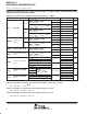
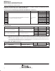
Timer_A (3 capture/compare registers) (continued)
P1.1
P1.5
P1.2
P1.6
P2.3
P1.3
P1.7
P2.4
Input
Divider
CLK
16-Bit Timer
SSEL0SSEL1
TACLK
ACLK
SMCLK
0
1
2
3
RC
INCLK
ID1
ID0
15
0
Data
32 kHz to 8 MHz
Timer Clock
POR/CLR
Mode
Control
MC1 MC0
Equ0
Carry/Zero
Set_TAIFG
16-Bit Timer
Capture
Mode
CCIS00CCIS01
CCI0A
CCI0B
GND
0
1
2
3
V
CC
CCI0 CCM00
CCM01
Capture/Compare
Register CCR0
15
0
Comparator 0
15
0
Output Unit 0
OM02 OM00OM01
Capture
EQU0
Capture/Compare Register CCR0Timer Bus
Capture
Mode
CCIS10CCIS11
CCI1A
CCI1B
GND
0
1
2
3
V
CC
CCI1 CCM10
CCM11
Capture/Compare
Register CCR1
15
0
Comparator 1
15
0
Output Unit 1
OM12 OM10OM11
Capture
EQU1
Capture/Compare Register CCR1
Capture
Mode
CCIS20CCIS21
CCI2A
CCI2B
GND
0
1
2
3
V
CC
CCI2 CCM20
CCM21
15
0
Comparator 2
15
0
Output Unit 2
OM22 OM20OM21
Capture
EQU2
Capture/Compare Register CCR2
P1.0
P2.1
P1.1
P2.2
P1.2
CAOUT
P1.3
ACLK
Out 0
Out 1
Out 2
Capture/Compare
Register CCR2
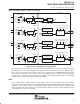
Figure 4. Timer_A, MSP430x11x1 Configuration
Two interrupt vectors are used by the Timer_A module. One individual vector is assigned to capture/compare
block CCR0, and one common interrupt vector is implemented for the timer and the other two capture/compare
blocks. The three interrupt events using the same vector are identified by an individual interrupt vector word.
The interrupt vector word is used to add an offset to the program counter to continue the interrupt handler
software at the corresponding program location. This simplifies the interrupt handler and gives each interrupt
event the same overhead of 5 cycles in the interrupt handler.
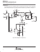
UART
Serial communication is implemented by using software and one capture/compare block. The hardware
supports the output of the serial-data stream, bit by bit, with the timing determined by the comparator/timer. The
data input uses the capture feature. The capture flag finds the start of a character, while the compare feature
latches the input-data stream, bit by bit. The software/hardware interface connects the mixed-signal controller
to external devices, systems, or networks.