
Mixed Signal Microcontroller Specification Sheet


MSP430x11x1
MIXED SIGNAL MICROCONTROLLER
SLAS241C – SEPTEMBER 1999 – REVISED JUNE 2000
23
POST OFFICE BOX 655303 • DALLAS, TEXAS 75265
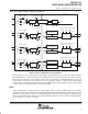
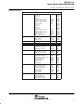
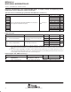
Comparator_A (continued)
The control bits are:
CAOUT, 05Ah, bit0, Comparator output
CAF, 05Ah, bit1, The comparator output is transparent or fed through a small filter
CA0, 05Ah, bit2, 0: Pin P2.3/CA0/TA1 is not connected to Comparator_A.
1: Pin P2.3/CA0/TA1 is connected to Comparator_A.
CA1, 05Ah, bit3, 0: Pin P2.4/CA1/TA2 is not connected to Comparator_A.
1: Pin P2.4/CA1/TA2 is connected to Comparator_A.
CACTL2.4
to
CATCTL2.7
05Ah, bit4,
05Ah, bit7,
Bits are implemented but do not control any hardware in this device.
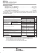
CAIFG, 059h, bit0, Comparator_A interrupt flag
CAIE, 059h, bit1, Comparator_A interrupt enable
CAIES, 059h, bit2, Comparator_A interrupt edge select bit
0: The rising edge sets the Comparator_A interrupt flag CAIFG
1: The falling edge set the Comparator_A interrupt flag CAIFG
CAON, 059h, bit3, The comparator is switched on.
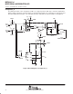
CAREF, 059h, bit4,5, Comparator_A reference
0: Internal reference is switched off, an external reference can be applied.
1: 0.25 × VCC reference selected.
2: 0.50 × VCC reference selected.
3: A diode reference selected.
CARSEL, 059h, bit6, An internal reference V
CAREF
, selected by CAREF bits, can be applied to
signal path CA0 or CA1. The signal V
CAREF
is only driven by a voltage
source if the value of CAREF control bits is 1, 2, or 3.
CAEX, 059h, bit7, The comparator inputs are exchanged, used to measure and compensate
the offset of the comparator.
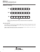
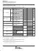
Eight additional bits are implemented into the Comparator_A module and enable the SW to switch off the input
buffer of port P2. A CMOS input buffer would dissipate supply current when the input is not near VSS or VCC.
Comparator_A port disable control bits CAPD0 to CAPD7 are initially reset, and the port input buffer is active.
The port input buffer is disabled if the appropriate control bit is set.