
Mixed Signal Microcontroller Specification Sheet


MSP430x11x1
MIXED SIGNAL MICROCONTROLLER
SLAS241C – SEPTEMBER 1999 – REVISED JUNE 2000
24
POST OFFICE BOX 655303 • DALLAS, TEXAS 75265
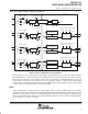
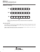
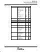
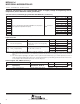
Comparator_A (continued)
CA1 CA0
CAEX
7
rw-(0)
CA
RSEL
rw-(0)
CA
REF1
rw-(0)
CA
REF0
rw-(0)
CAON
rw-(0)
CAIES
rw-(0)
CAIE
rw-(0)
CAIFG
0
rw-(0)
CACTL1
059h
CACTL
2.7
7
rw-(0)
CACTL
2.6
rw-(0)
CACTL
2.5
rw-(0) rw-(0) rw-(0) rw-(0)
CAF
rw-(0)
CAOUT
0
r-(0)
CACTL2
05Ah
CACTL
2.4
7
rw-(0)
rw-(0) rw-(0) rw-(0)
CAPD3
rw-(0)
CAPD2
rw-(0)
CAPD1
rw-(0)
CAPD0
0
rw-(0)
CAPD
05Bh
CAPD4CAPD5CAPD6CAPD7
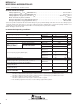
NOTE:
Ensure that the comparator input terminals are connected to signal, power, or ground level.
Otherwise, floating levels may cause unexpected interrupts and current consumption may be
increased.
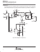
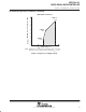
slope a/d conversion
The Comparator_A is well suited for use in single or multiple-slope conversions. The internal-reference levels
may be used to set a reference during timing measurement of charge or discharge operations. They can also
be used externally to bias analog circuitry.
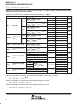
Voltage, current, and resistive or capacitive sensor measurements are basic functions. The sensors sense
physical conditions like temperature, pressure, acceleration, etc.