
Mixed Signal Microcontroller Specification Sheet


MSP430x11x1
MIXED SIGNAL MICROCONTROLLER
SLAS241C – SEPTEMBER 1999 – REVISED JUNE 2000
34
POST OFFICE BOX 655303 • DALLAS, TEXAS 75265
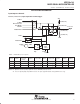
electrical characteristics over recommended ranges of supply voltage and operating free-air
temperature (unless otherwise noted) (continued)
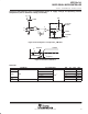
VCC
POR
V
t
V
(POR)
V
(min)
POR
No POR
Figure 11. Power-On Reset (POR) vs Supply Voltage
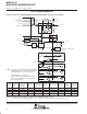
0
0.2
0.6
1.0
1.2
1.8
2.0
–40 –20 0 20 40 60 80
Temperature [°C]
V POR [V]
1.6
1.4
0.8
0.4
1.2
1.5
1.8
0.8
1.1
1.4
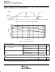
25°C
Max
Min
Figure 12. V
(POR)
vs Temperature
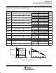
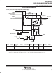
crystal oscillator,LFXT1
PARAMETER TEST CONDITIONS MIN TYP MAX UNIT
C
(XIN)
In
p
ut ca
p
acitance
XTS=0; LF mode selected.
V
CC
= 2.2 V / 3 V
12
p
F
C
(XIN)
Inp
u
t
capacitance
XTS=1; XT1 mode selected.
V
CC
= 2.2 V / 3 V (Note 19)
2
pF
C
(XOUT)
Out
p
ut ca
p
acitance
XTS=0; LF mode selected.
V
CC
= 2.2 V / 3 V
12
p
F
C
(XOUT)
Out ut
ca acitance
XTS=1; XT1 mode selected.
V
CC
= 2.2 V / 3 V (Note 19)
2
F
NOTE 19: Requires external capacitors at both terminals. Values are specified by crystal manufacturers.
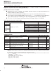
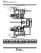
RAM
PARAMETER MIN NOM MAX UNIT
V
(RAMh)
CPU halted (see Note 20) 1.6 V
NOTE 20: This parameter defines the minimum supply voltage V
CC
when the data in the program memory RAM remains unchanged. No program
execution should happen during this supply voltage condition.