
Mixed Signal Microcontroller Specification Sheet

MSP430x11x1
MIXED SIGNAL MICROCONTROLLER
SLAS241C – SEPTEMBER 1999 – REVISED JUNE 2000
42
POST OFFICE BOX 655303 • DALLAS, TEXAS 75265
APPLICATION INFORMATION
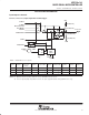
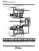
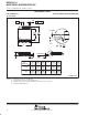
Port P2, unbonded bits P2.6 and P2.7
EN
D
0
1
0
1
Interrupt
Edge
Select
EN
Set
Q
P2IE.x
P2IFG.x
P2IRQ.x
Interrupt
Flag
P2IES.x
P2SEL.x
Module X IN
P2IN.x
P2OUT.x
Module X OUT
Direction Control
From Module
P2DIR.x
P2SEL.x
Bus Keeper
0
1
0: Input
1: Output
Node Is Reset With PUC
PUC
NOTE: x = Bit/identifier, 6 to 7 for port P2 without external pins
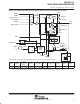
P2Sel.x
P2DIR.x
Direction
control from
module
P2OUT.x Module X OUT P2IN.x Module X IN P2IE.x P2IFG.x P2IES.x
P2Sel.6 P2DIR.6 P2DIR.6 P2OUT.6 VSS P2IN.6 unused P2IE.6 P2IFG.6 P2IES.6
P2Sel.7 P2DIR.7 P2DIR.7 P2OUT.7 VSS P2IN.7 unused P2IE.7 P2IFG.7 P2IES.7
NOTE: A good use of the unbonded bits 6 and 7 of port P2 is to use the interrupt flags. The interrupt flags can not be influenced from any signal
other than from software. They work then as a soft interrupt.
JTAG fuse check mode
MSP430 devices that have the fuse on the TEST terminal have a fuse check mode that tests the continuity of
the fuse the first time the JTAG port is accessed after a power-on reset (POR). When activated, a fuse check
current can flow from the TEST pin to ground if the fuse is not burned. Care must be taken to avoid accidentally
activating the fuse check mode and increasing overall system power consumption.
When the TEST pin is taken back low after a test or programming session, the fuse check mode and sense
currents are terminated.