
Stereo System User Manual

Reduced Power Modes
2-37
MSP50C614 Architecture
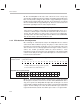
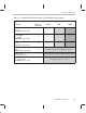
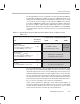
Table 2–3. Programmable Bits Needed to Control Reduced Power Modes
→ deeper sleep … relatively less power →
Control Bit
Label for
Control Bit
LIGHT MID DEEP
Idle state clock control
bit 10
ClkSpdCtrl register (0x3D)
A 0 1 1
Enable reference oscillator
bit 09 : CRO or
bit 08 : RTO
ClkSpdCtrl register (0x3D)
B 1 1 0
ARM
bit 14
IntGenCtrl register (0x38)
C 0 1 1
Enable PDM pulsing
bit 02
DAC Control register (0x34)
D Should be cleared before any IDLE instruction.
IDLE instruction
(executes the mode)
E Same instruction is used to engage any of the modes.
PLL multiplier
bits 07 through 00
ClkSpdCtrl register (0x3D)
F Programmed value is 0 … 255 .