
User manual

www.ti.com
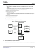
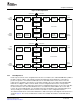
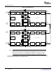
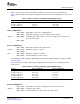
1.3 Functional Block Diagram
Slave
config
bus
Interface
Master
config
Interface
bus
VLYNQmodule
VLYNQregister
access
CPU/EDMA initiated
transfersto
remotedevice
Offchip
(remote)
deviceaccess
CPU/EDMA
memory
System
VSCRUN
VCLK
VRXDx
VTXDx
GEMINTC
VLQINT
Inthesesignals,
x=anumberfrom3to0
1.4 Industry Standard(s) Compliance Statement
Introduction
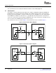
• Symmetric Operation:
– Tx pins on first device connect to Rx pins on second device and vice versa.
– Data pin widths are automatically detected after reset (including connections to legacy VLYNQ
devices).
– Request packets, response packets, and flow control information are all multiplexed and sent
across the same physical pins.
– Supports both Host/Peripheral and Peer to Peer communication models.
• Simple block code packet formatting (8b/10b).
• Supports in-band and flow control:
– No extra pins are needed.
– Allows the receiver to momentarily throttle the transmitter back when overflow is about to occur.
– Uses the special built-in block code capability to interleave flow control information seamlessly with
user data.
• Automatic packet formatting optimizations.
• Internal loopback modes are provided.
• Connects to legacy VLYNQ devices.
Figure 1 shows a functional block diagram of the VLYNQ port.
Figure 1. VLYNQ Port Functional Block Diagram
VLYNQ is an interface defined by Texas Instruments and does not conform to any other industry standard.
SPRUF89 – October 2007 VLYNQ Port 11
Submit Documentation Feedback