
User manual

www.ti.com
2.5 VLYNQ Functional Description
Address
translation
commands
Outbound
Outbound
command
FIFO
data
Return
FIFO
data
FIFO
Return
command
Inbound
FIFO
Registers
translation
Address
TxSM
8B/10B
encoding
Serializer
commands
Inbound
RxSM Deserializer
decoding
8B/10B
Serial
TxData
Serial
TxClk
Serial
RxClk
Serial
RxData
Master
configbus
interface
Systemclock VLYNQclock
Slave
configbus
interface
(FIFO3)
(FIFO2)
(FIFO0)
(FIFO1)
2.5.1 Write Operations
Peripheral Architecture
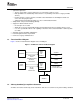
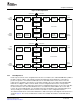
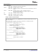
The VLYNQ core supports both host-to-peripheral and peer-to-peer communication models and is
symmetrical. The VLYNQ module structure is shown in Figure 4 .
Figure 4. VLYNQ Module Structure
The VLYNQ core module implements two 32-bit configuration bus interfaces. Transmit operations and
control register access require the slave configuration bus interface. The master configuration bus
interface is required for receive operations. Converting to and from the 32-bit bus to the external serial
interface requires serializer and deserializer blocks.
8b/10b block coding encodes data on the serial interface. Frame delineation, initialization, and flow control
use special overhead code groups.
FIFOs buffer the entire burst on the bus for maximum performance, thus minimizing bus latency. Using
write operations of each VLYNQ module interfaced is typically recommended to ensure the best
performance on both directions of the link.
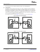
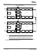
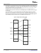
Write requests that initiate from the slave configuration bus interface of the local device write to the
outbound command (CMD) FIFO. Data is subsequently read from the FIFO and encapsulated in a write
request packet. The address is translated, and the packet is encoded and serialized before being
transmitted to remote device. The remote device subsequently deserializes and decodes the receive data
and writes it into the inbound CMD FIFO. A write operation initiates on the remote device’s master
configuration bus interface after reading the address and data from the FIFO.
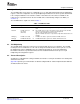
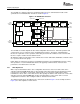
The data flow between two VLYNQs that are connected is shown in Figure 5 . In the example shown in
Figure 5 , the write originates from the device.
14 VLYNQ Port SPRUF89 – October 2007
Submit Documentation Feedback