
User manual

SWRU268A
October 2010
1/2
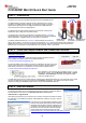
Target Boards
Battery Sensor
(End
-
Device)
Battery Sensor
(End-Device)
USB Stick
(Coordinator)
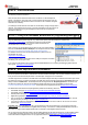
CC2530ZNP Mini Kit Quick Start Guide
STEP 1 – Introduction
This guide describes how to set up a CC2530 ZigBee® Network Processor (ZNP)
development kit using the preprogrammed devices of the CC2530ZNP Mini Kit.
The ZigBee Network Processor development kit is designed to give a simple
introduction to ZigBee wireless networks. The hardware consists of a CC2530
ZigBee device preprogrammed with ZigBee software and an MSP430F2274
microcontroller that controls the ZigBee device.
The development kit demonstrates examples of typical sensor networks with
temperature, light, voltage, and movement sensors.
The target board connected to the USB stick is programmed with a coordinator
sample application. The coordinator sets up the network and configures the ZigBee
network parameters. A ZigBee system can only have one coordinator.
The battery powered sensors are end-devices that periodically report their key
data to the coordinator. The devices can also be programmed as routers. Routers are typically used to extend the
ZigBee network since they can route messages from other devices. Note that hardware for all the target boards is
identical. Each of the boards can be programmed to be coordinator, router, or end-device.
STEP 2 – Install the sample software and connect the USB stick
Download the CC2530ZNP example software from
http://www.ti.com/cc2530znp
Double-click the installer file to install the example software package and drivers.
After installation the default location for the sample software is
C:\Texas Instruments\CC2530ZNP Mini Kit
Connect the USB stick to a USB port on the PC. The Windows new device driver will
request a new device driver to be installed. Normally the driver should be detected
automatically. If the driver is not detected it can be found at the default location:
C:\Texas Instruments\CC2530ZNP Mini Kit\Drivers
After installation a new COM port will be installed on the PC. To see
the COM port number, open the Windows Control panel – System
– Hardware – Device Manager and check the COM port number
under Ports (COM and LPT).
The USB stick serves both as a virtual serial port interface and as debugger/programmer. This means that during normal
operation the USB stick should be connected to the coordinator target board. The USB stick can also be used to
program and debug the end-device target boards using the IAR Embedded Workbench.
STEP 3 – Start the network
The ZigBee coordinator on the USB stick connects to the PC using a virtual USB serial port.
The serial port interface can be accessed through a terminal program. The Windows default
terminal interface can be found on the Windows Start menu - Accessories-
Communication – Hyperterminal.
After starting HyperTerminal, give a name to the connection and select the COM port used by
the USB stick. In the COM port properties, select 9600 baud, 8 data bits, no parity, 1 stop bit,
no flow control
Push the button on the target board to display the status
window of the network after the terminal has connected.
Information about the ZNP and device is displayed. The
coordinator is now ready to connect to other devices on
the network. For more information about the message
format, please see the Simple Application wiki page:
http://processors.wiki.ti.com/index.php/Simple_Applications_Examples
USB StickTarget Board