
Datasheet


Inverting Amplifier
4-6
Example Circuits
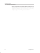
4.4 Inverting Amplifier
Figure 4–3 shows area 300 equipped with a single operational amplifier con-
figured as an inverting amplifier using dual power supplies.
Basic setup is done by choice of input and feedback resistors. The transfer
function for the circuit as shown is:
V
OUT
–V
IN
R
302
R
304
To cancel the effects of input bias current, set R306 = R302 || R304, or use a
0-Ω jumper for R306 if the operational amplifier is a low input bias operational
amplifier.
Figure 4–3. Inverting Amplifier with Dual Supply Using Area 300
C304 C303
C305 C306
V3+
V3–
V3+
GND3
V3–
Power Supply Bypass
+
–
7
6
4
3
2
V3+
V3–
R302
C302
R301
C301
R303
R304
R307
R308
R309
R306
C309
C308
3OUT
301–
302–
303+
304+
R311
C
R
A
U302
R310
Voltage Reference
U301
V3+
VREF3
R312
+
–
V
in
V
OUT
= –V
IN
R302
R304
R306 = R302 II R304,
or Short if Using Low
Input Bias Op Amp
Not Used
0.1 µF 10 µF
0.1 µF 10 µF
8
3/SD
3 FLT
R305
C307
C310
Jumper