Data Manual March 2004 PCIBus Solutions SCPS065D
Contents Section 1 2 3 Title Introduction . . . . . . . . . . . . . . . . . . . . . . . . . . . . . . . . . . . . . . . . . . . . . . . . . . . . . . 1.1 Description . . . . . . . . . . . . . . . . . . . . . . . . . . . . . . . . . . . . . . . . . . . . . . . . . 1.2 Features . . . . . . . . . . . . . . . . . . . . . . . . . . . . . . . . . . . . . . . . . . . . . . . . . . . 1.3 Related Documents . . . . . . . . . . . . . . . . . . . . . . . . . . . . . . . . . . . . . . . . . . 1.4 Trademarks . . . . .
4 iv 3.7.5 Using Serialized IRQSER Interrupts . . . . . . . . . . . . . . . . . . . 3.7.6 SMI Support in the PCI1520 . . . . . . . . . . . . . . . . . . . . . . . . . . 3.8 Power Management Overview . . . . . . . . . . . . . . . . . . . . . . . . . . . . . . . . 3.8.1 Integrated Low-Dropout Voltage Regulator (LDO-VR) . . . . 3.8.2 Clock Run Protocol . . . . . . . . . . . . . . . . . . . . . . . . . . . . . . . . . 3.8.3 CardBus PC Card Power Management . . . . . . . . . . . . . . . . 3.8.
.29 4.30 4.31 4.32 4.33 4.34 4.35 4.36 4.37 4.38 4.39 5 System Control Register . . . . . . . . . . . . . . . . . . . . . . . . . . . . . . . . . . . . . . Multifunction Routing Register . . . . . . . . . . . . . . . . . . . . . . . . . . . . . . . . Retry Status Register . . . . . . . . . . . . . . . . . . . . . . . . . . . . . . . . . . . . . . . . Card Control Register . . . . . . . . . . . . . . . . . . . . . . . . . . . . . . . . . . . . . . . . Device Control Register . . . . . . . . . . . . . . .
6 7 8 vi 5.23 ExCA Memory Windows 0−4 Page Registers . . . . . . . . . . . . . . . . . . . 5−24 CardBus Socket Registers (Functions 0 and 1) . . . . . . . . . . . . . . . . . . . . . . 6−1 6.1 Socket Event Register . . . . . . . . . . . . . . . . . . . . . . . . . . . . . . . . . . . . . . . 6−2 6.2 Socket Mask Register . . . . . . . . . . . . . . . . . . . . . . . . . . . . . . . . . . . . . . . . 6−3 6.3 Socket Present-State Register . . . . . . . . . . . . . . . . . . . . . . . . . . . . . . . .
List of Illustrations Figure Title 2−1 PCI1520 GHK-Package Terminal Diagram . . . . . . . . . . . . . . . . . . . . . . . . . . . 2−2 PCI1520 PDV-Package Terminal Diagram . . . . . . . . . . . . . . . . . . . . . . . . . . . . 3−1 PCI1520 Simplified Block Diagram . . . . . . . . . . . . . . . . . . . . . . . . . . . . . . . . . . 3−2 3-State Bidirectional Buffer . . . . . . . . . . . . . . . . . . . . . . . . . . . . . . . . . . . . . . . . . 3−3 TPS222X Typical Application . . . . . . . . . . . . . . . . .
List of Tables Table Title 2−1 Signal Names by PDV Terminal Number . . . . . . . . . . . . . . . . . . . . . . . . . . . . . 2−2 Signal Names by GHK Terminal Number . . . . . . . . . . . . . . . . . . . . . . . . . . . . . 2−3 CardBus PC Card Signal Names Sorted Alphabetically . . . . . . . . . . . . . . . . 2−4 16-Bit PC Card Signal Names Sorted Alphabetically . . . . . . . . . . . . . . . . . . . 2−5 Power Supply Terminals . . . . . . . . . . . . . . . . . . . . . . . . . . . . . . . . . . . . . . . . . .
4−9 Multifunction Routing Register Description . . . . . . . . . . . . . . . . . . . . . . . . . . . 4−10 Retry Status Register Description . . . . . . . . . . . . . . . . . . . . . . . . . . . . . . . . . . 4−11 Card Control Register Description . . . . . . . . . . . . . . . . . . . . . . . . . . . . . . . . . . 4−12 Device Control Register Description . . . . . . . . . . . . . . . . . . . . . . . . . . . . . . . . 4−13 Diagnostic Register Description . . . . . . . . . . . . . . . . . . . . . . . . . . . .
x
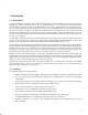
1 Introduction 1.1 Description The Texas Instruments PCI1520, a 208-terminal dual-slot CardBus controller designed to meet the PCI Bus Power Management Interface Specification for PCI to CardBus Bridges, is an ultralow-power high-performance PCI-to-CardBus controller that supports two independent card sockets compliant with the PC Card Standard (rev. 7.1). The PCI1520 provides features that make it the best choice for bridging between PCI and PC Cards in both notebook and desktop computers.
• Up to five general-purpose I/Os • Programmable output select for CLKRUN • Multifunction PCI device with separate configuration space for each socket • Five PCI memory windows and two I/O windows available for each 16-bit interface • Two I/O windows and two memory windows available to each CardBus socket • Exchangeable-card-architecture- (ExCA-) compatible registers are mapped in memory and I/O space • Intel 82365SL-DF and 82365SL register compatible • Ring indicate, SUSPEND, PCI CLKRUN, an
1.6 PCI1520 Data Manual Document History DATE PAGE NUMBER REVISION 01/2003 2−1 Corrected part number typo in the first sentence of the page 01/2003 2−15 Corrected description of EEPROM detection scheme. EEPROM detection happens on deassertion of GRST rather than PRST. 01/2003 3−2 Added new subsection 3.4.
1−4
2 Terminal Descriptions The PCI1520 is available in three packages, a 208-terminal quad flatpack (PDV) and two 209-terminal MicroStar BGA packages (GHK/ZHK). The GHK and ZHK packages are mechanically and electrically identical, but the ZHK is a lead-free (Pb, atomic number 82) design. Throughout the remainder of this manual (except Chapter 8), only the GHK designator is used for either the GHK or ZHK package. The terminal layout for the GHK package is shown in Figure 2−1.
AD10 AD9 AD8 C/BE0 AD7 GND AD6 AD5 AD4 AD3 AD2 AD1 AD0 VCC B_CCD1//B_CD1 B_CAD0//B_D3 B_CAD2//B_D11 B_CAD1//B_D4 B_CAD4//B_D12 B_CAD3//B_D5 B_CAD6//B_D13 B_CAD5//B_D6 B_RSVD//B_D14 GND B_CAD7//B_D7 B_CAD8//B_D15 B_CC/BE0//B_CE1 B_CAD9//B_A10 VR_EN B_CAD10//B_CE2 B_CAD11//B_OE B_CAD12//B_A11 B_CAD13//B_IORD B_CAD15//B_IOWR B_CAD14//B_A9 B_CAD16//B_A17 B_CC/BE1//B_A8 B_RSVD//B_A18 VCC B_CPAR//B_A13 B_CBLOCK//B_A19 B_CPERR//B_A14 GND B_CSTOP//B_A20 B_CGNT//B_WE B_CDEVSEL//B_A21 VCCB B_CCLK//B_A16 B_CTRDY//B_A2
Table 2−1 and Table 2−2 list the terminal assignments arranged in terminal-number order, with corresponding signal names for both CardBus and 16-bit PC Cards; Table 2−1 is for terminals on the PDV package and Table 2−2 is for terminals on the GHK package.
Table 2−1. Signal Names by PDV Terminal Number (Continued) SIGNAL NAME TERM. NO. 16-Bit PC Card SIGNAL NAME CardBus PC Card 16-Bit PC Card TERM. NO.
Table 2−2. Signal Names by GHK Terminal Number SIGNAL NAME TERM. NO. SIGNAL NAME TERM. NO. CardBus PC Card 16-Bit PC Card A04 AD12 AD12 E07 PERR PERR H06 AD2 AD2 A05 PAR PAR E08 FRAME FRAME H14 A_CSTSCHG A_BVD1(STSCHG/RI) A06 GND GND E09 AD19 AD19 H15 A_CCLKRUN A_WP(IOIS16) A07 VCC AD18 VCC AD18 E10 IDSEL IDSEL H17 A_CAUDIO A_BVD2(SPKR) E11 AD27 AD27 H18 A_CSERR A_WAIT A08 CardBus PC Card SIGNAL NAME 16-Bit PC Card TERM. NO.
Table 2−2. Signal Names by GHK Terminal Number (Continued) SIGNAL NAME TERM. NO. CardBus PC Card 16-Bit PC Card M15 A_CFRAME A_A23 M17 A_CC/BE2 A_A12 M18 A_CAD17 M19 N01 SIGNAL NAME TERM. NO. SIGNAL NAME TERM. NO.
Table 2−3. CardBus PC Card Signal Names Sorted Alphabetically TERM NO. SIGNAL NAME PDV GHK A_CAD0 84 P11 A_CAD1 86 A_CAD2 85 A_CAD3 88 A_CAD4 A_CAD5 A_CAD6 A_CAD7 A_CAD8 94 A_CAD9 97 A_CAD10 98 A_CAD11 99 A_CAD12 100 A_CAD13 101 A_CAD14 103 A_CAD15 102 A_CAD16 A_CAD17 TERM. NO. SIGNAL NAME PDV GHK A_CDEVSEL 113 N15 W12 A_CFRAME 119 R11 A_CGNT 112 U12 A_CINT 87 V12 90 R12 89 93 TERM. NO.
Table 2−3. CardBus PC Card Signal Names Sorted Alphabetically (Continued) TERM NO. SIGNAL NAME PDV GHK B_CC/BE0 27 K05 B_CC/BE1 37 B_CC/BE2 52 B_CC/BE3 TERM NO. SIGNAL NAME PDV GHK C/BE2 193 F08 M06 C/BE3 164 T01 CLOCK 154 64 U07 DATA 155 B_CCD1 15 H05 DEVSEL B_CCD2 75 P09 FRAME TERM NO.
Table 2−4. 16-Bit PC Card Signal Names Sorted Alphabetically TERM. NO. SIGNAL NAME TERM. NO. SIGNAL NAME TERM NO.
Table 2−4. 16-Bit PC Card Signal Names Sorted Alphabetically (Continued) TERM NO. SIGNAL NAME PDV GHK B_D2 80 P10 B_D3 16 B_D4 18 B_D5 20 B_D6 B_D7 B_D8 B_D9 TERM NO. SIGNAL NAME PDV GHK C/BE2 193 F08 H03 C/BE3 164 H01 CLOCK 154 J02 DATA 155 22 J05 DEVSEL 25 K02 FRAME 77 V10 79 R10 B_D10 82 B_D11 B_D12 TERM NO.
The terminals are grouped in tables by functionality, such as PCI system function, power-supply function, etc. The terminal numbers are also listed for convenient reference. Table 2−5. Power Supply Terminals TERMINAL NO. NAME I/O DESCRIPTION PDV GHK GND 6, 24, 43, 62, 95, 110, 147, 166, 185, 199 A06, A09, A14, E01, F19, K01, P01, R19, W06, W14 − VCC 14, 39, 70, 91, 118, 133, 143, 174, 195 A07, A12, G01, G19, J19, N01, N19, W08, W13 − VCCA 114 P19 − Clamp voltage for PC Card A interface.
Table 2−7. PCI System Terminals TERMINAL NO. NAME I/O DESCRIPTION GHK GRST 177 C11 I Global reset. When the global reset is asserted, the GRST signal causes the PCI1520 to place all output buffers in a high-impedance state and reset all internal registers. When GRST is asserted, the device is completely in its default state. For systems that require wake-up from D3, GRST normally is asserted only during initial boot.
Table 2−8. PCI Address and Data Terminals TERMINAL NO. NAME I/O DESCRIPTION I/O PCI address/data bus. These signals make up the multiplexed PCI address and data bus on the primary interface. During the address phase of a primary-bus PCI cycle, AD31−AD0 contain a 32-bit address or other destination information. During the data phase, AD31−AD0 contain data. B14 F08 F06 G06 I/O PCI-bus commands and byte enables. These signals are multiplexed on the same PCI terminals.
Table 2−9. PCI Interface Control Terminals TERMINAL NO. I/O DESCRIPTION F07 I/O PCI device select. The PCI1520 asserts DEVSEL to claim a PCI cycle as the target device. As a PCI initiator on the bus, the PCI1520 monitors DEVSEL until a target responds. If no target responds before timeout occurs, then the PCI1520 terminates the cycle with an initiator abort. 194 E08 I/O PCI cycle frame. FRAME is driven by the initiator of a bus cycle.
Table 2−10. Multifunction and Miscellaneous Terminals TERMINAL NO. NAME MFUNC0 PDV GHK 156 D19 I/O DESCRIPTION I/O Multifunction terminal 0. MFUNC0 can be configured as parallel PCI interrupt INTA, GPI0, GPO0, socket activity LED output, ZV switching output, CardBus audio PWM, GPE, or a parallel IRQ. See Section 4.30, Multifunction Routing Register, for configuration details. Multifunction terminal 1.
Table 2−11.
Table 2−12. 16-Bit PC Card Interface Control Terminals (Slots A and B) TERMINAL NUMBER NAME SLOT A† PDV BVD1 (STSCHG/RI) 141 GHK H14 SLOT B‡ PDV 73 I/O DESCRIPTION GHK U09 I Battery voltage detect 1. BVD1 is generated by 16-bit memory PC Cards that include batteries. BVD1 is used with BVD2 as an indication of the condition of the batteries on a memory PC Card. Both BVD1 and BVD2 are high when the battery is good. When BVD2 is low and BVD1 is high, the battery is weak and should be replaced.
Table 2−12. 16-Bit PC Card Interface Control Terminals (Slots A and B) (Continued) TERMINAL NUMBER NAME OE READY (IREQ) SLOT A† SLOT B‡ PDV GHK PDV GHK 99 W15 31 L03 138 H19 69 V08 I/O DESCRIPTION O Output enable. OE is driven low by the PCI1520 to enable 16-bit memory PC Card data output during host memory read cycles. I Ready. The ready function is provided by READY when the 16-bit PC Card and the host socket are configured for the memory-only interface.
Table 2−13. CardBus PC Card Interface System Terminals (Slots A and B) TERMINAL NUMBER NAME SLOT A† PDV GHK SLOT B‡ PDV I/O DESCRIPTION GHK CCLK 115 M14 48 P06 O CardBus clock. CCLK provides synchronous timing for all transactions on the CardBus interface. All signals except CRST, CCLKRUN, CINT, CSTSCHG, CAUDIO, CCD2, CCD1, CVS2, and CVS1 are sampled on the rising edge of CCLK, and all timing parameters are defined with the rising edge of this signal.
Table 2−14.
Table 2−15. CardBus PC Card Interface Control Terminals (Slots A and B) TERMINAL NUMBER NAME SLOT A† SLOT B‡ I/O DESCRIPTION CardBus audio. CAUDIO is a digital input signal from a PC Card to the system speaker. The PCI1520 supports the binary audio mode and outputs a binary signal from the card to SPKROUT. PDV GHK PDV GHK CAUDIO 140 H17 72 V09 I CBLOCK 108 N14 41 N03 I/O CCD1 CCD2 83 144 U11 G18 15 75 H05 P09 I CardBus detect 1 and CardBus detect 2.
2−22
3 Feature/Protocol Descriptions The following sections give an overview of the PCI1520. Figure 3−1 shows a simplified block diagram of the PCI1520. The PCI interface includes all address/data and control signals for PCI protocol. The interrupt interface includes terminals for parallel PCI, parallel ISA, and serialized PCI and ISA signaling. Miscellaneous system interface terminals include multifunction terminals: SUSPEND, RI_OUT/PME (power management control signal), and SPKROUT.
The power-down sequence is: 1. Assert GRST to the device to disable the outputs during power down. Output drivers must be powered down in the high-impedance state to prevent high current levels through the clamp diodes to the 5-V clamping rails (VCCA, VCCB, and VCCP). 2. Remove the clamp voltage. 3. Remove the 3.3-V power from VCC. NOTE: The clamp voltage can be ramped up or ramped down along with the 3.3-V power. The voltage difference between VCC and the clamp voltage must remain within 3.6 V. 3.
3.4.2 PCI Bus Lock (LOCK) The bus-locking protocol defined in the PCI Local Bus Specification is not highly recommended, but is provided on the PCI1520 as an additional compatibility feature. The PCI LOCK signal can be routed to the MFUNC4 terminal by setting the appropriate values in bits 19−16 of the multifunction routing register. See Section 4.30, Multifunction Routing Register, for details.
3.5 PC Card Applications This section describes the PC Card interfaces of the PCI1520. • • • • • • 3.5.1 Card insertion/removal and recognition P2C power-switch interface Zoomed video support Speaker and audio applications LED socket activity indicators CardBus socket registers PC Card Insertion/Removal and Recognition The PC Card Standard (release 7.
Power Supply TPS222X 12 V 5V 3.3 V 12 V 5V 3.3 V Supervisor RESET RESET PCI1520 (PCMCIA Controller) CLOCK DATA LATCH AVPP AVCC AVCC VPP1 VPP2 VCC VCC PC Card A VPP1 VPP2 VCC VCC PC Card B AVCC BVPP BVCC BVCC BVCC Figure 3−3. TPS222X Typical Application Table 3−2.
Speakers CRT Motherboard PCI Bus VGA Controller Audio Codec Zoomed Video Port 19 PCM Audio Input PC Card 19 4 PC Card Interface PCI1520 Video Audio 4 Figure 3−4. Zoomed Video Implementation Using the PCI1520 Not shown in Figure 3−4 is the multiplexing scheme used to route either socket 0 or socket 1 ZV source to the graphics controller. The PCI1520 provides ZVSTAT, ZVSEL0, and ZVSEL1 signals on the multifunction terminals to switch external bus drivers.
Table 3−3. Functionality of the ZV Output Signals INPUTS OUTPUTS PORTSEL SOCKET 0 ENABLE SOCKET 1 ENABLE ZVSEL0 ZVSEL1 ZVSTAT X 0 0 1 1 0 0 1 X 0 1 1 0 0 1 1 0 1 1 X 1 1 0 1 1 1 0 0 1 1 Also shown in Figure 3−5 is a third ZV input that can be provided from a source such as a high-speed serial bus like IEEE 1394. The ZVSTAT signal provides a mechanism to switch the third ZV source.
There are two types of PC Card controllers to consider. • Legacy controller not using the standardized ZV register model Software reads bit 10 (STDZVREG) of the socket control register (CardBus socket address + 10h) to determine if the standardized zoomed-video register model is supported. If the bit returns 0, then software must use legacy code to enable zoomed video.
Table 3−5. Integrated Pullup Resistors TERM. NUMBER SOCKET A SIGNAL NAME A14/CPERR 3.5.7 TERM.
System Core Logic BINARY_SPKR SPKROUT Speaker Subsystem PCI1520 CAUDPWM PWM_SPKR Figure 3−6. Sample Application of SPKROUT and CAUDPWM 3.5.8 LED Socket Activity Indicators The socket activity LEDs are provided to indicate when a PC Card is being accessed. The LEDA1 and LEDA2 signals can be routed to the multifunction terminals. When configured for LED outputs, these terminals output an active high signal to indicate socket activity.
Table 3−6. CardBus Socket Registers REGISTER NAME OFFSET Socket event 00h Socket mask 04h Socket present state 08h Socket force event 0Ch Socket control 10h Reserved 14h−1Ch Socket power management 20h 3.6 Serial-Bus Interface The PCI1520 provides a serial-bus interface to load subsystem identification information and selected register defaults from a serial EEPROM, and to provide a PC Card power-switch interface alternative to P2C. See Section 3.5.
in Figure 3−9. The end of a requested data transfer is indicated by a stop condition, which is signaled by a low-to-high transition of SDA while SCL is in the high state, as shown in Figure 3−9. Data on SDA must remain stable during the high state of the SCL signal, as changes on the SDA signal during the high state of SCL are interpreted as control signals, that is, a start or a stop condition. SDA SCL Start Condition Stop Condition Change of Data Allowed Data Line Stable, Data Valid Figure 3−9.
Slave Address S Word Address b6 b5 b4 b3 b2 b1 b0 0 A Data Byte b7 b6 b5 b4 b3 b2 b1 b0 A b7 b6 b5 b4 b3 b2 b1 b0 A P R/W A = Slave Acknowledgement S/P = Start/Stop Condition Figure 3−11. Serial-Bus Protocol − Byte Write Figure 3−12 illustrates a byte read. The read protocol is very similar to the write protocol, except the R/W command bit must be set to 1 to indicate a read-data transfer. In addition, the PCI1520 master must acknowledge reception of the read bytes from the slave transmitter.
Table 3−7.
Table 3−8. PCI1520 Registers Used to Program Serial-Bus Devices PCI OFFSET REGISTER NAME DESCRIPTION B0h Serial-bus data Contains the data byte to send on write commands or the received data byte on read commands. B1h Serial-bus index The content of this register is sent as the word address on byte writes or reads. This register is not used in the quick command protocol. B2h Serial-bus slave address Write transactions to this register initiate a serial-bus transaction.
Table 3−9.
3.7.2 Interrupt Masks and Flags Host software may individually mask (or disable) most of the potential interrupt sources listed in Table 3−10 by setting the appropriate bits in the PCI1520. By individually masking the interrupt sources listed, software can control those events that cause a PCI1520 interrupt. Host software has some control over the system interrupt the PCI1520 asserts by programming the appropriate routing registers.
PCI1520 MFUNC1 IRQ3 PIC MFUNC2 IRQ4 MFUNC3 IRQ5 MFUNC4 IRQ10 MFUNC5 IRQ11 MFUNC6 IRQ15 Figure 3−14. IRQ Implementation Power-on software is responsible for programming the multifunction routing register to reflect the IRQ configuration of a system implementing the PCI1520. The multifunction routing register is shared between the two PCI1520 functions, and only one write to function 0 or 1 is necessary to configure the MFUNC6−MFUNC0 signals. Writing to function 0 only is recommended.
Table 3−12. SMI Control BIT NAME FUNCTION SMIROUTE This shared bit controls whether the SMI interrupts are sent as a CSC interrupt or as IRQ2. SMISTAT This socket dependent bit is set when an SMI interrupt is pending. This status flag is cleared by writing back a 1. SMIENB When set, SMI interrupt generation is enabled. This bit is shared by functions 0 and 1. If CSC SMI interrupts are selected, then the SMI interrupt is sent as the CSC on a per-socket basis.
The PCI1520 restarts the PCI clock using the CLKRUN protocol under any of the following conditions: • A 16-bit PC Card IREQ or a CardBus CINT has been asserted by either card. • A CardBus CBWAKE (CSTSCHG) or 16-bit PC Card STSCHG/RI event occurs in either socket. • A CardBus attempts to start the CCLK using CCLKRUN. • A CardBus card arbitrates for the CardBus bus using CREQ. 3.8.
RESET GNT SUSPEND PCLK External Terminals Internal Signals RESETIN SUSPENDIN PCLKIN Figure 3−15. Signal Diagram of Suspend Function 3.8.6 Requirements for Suspend Mode The suspend mode prevents the clearing of all register contents on the assertion of reset (PRST or GRST) which would require the reconfiguration of the PCI1520 by software.
RI_OUT Function CSTSMASK PC Card Socket 0 CSC Card I/F RINGEN RI CDRESUME RIENB CSC RI_OUT CSTSMASK PC Card Socket 1 CSC Card I/F RINGEN RI CDRESUME CSC Figure 3−16. RI_OUT Functional Diagram RI from the 16-bit PC Card interface is masked by bit 7 (RINGEN) in the ExCA interrupt and general control register (ExCA offset 03h/43h/803h, see Section 5.4). This is programmed on a per-socket basis and is only applicable when a 16-bit card is powered in the socket.
NOTE 1: In the D0-uninitialized state, the PCI1520 does not generate PME and/or interrupts. When the IO_EN and MEM_EN bits (bits 0 and 1) of the command register (PCI offset 04h, see Section 4.4) are both set, the PCI1520 switches the state to D0-active. Transition from D3cold to the D0-uninitialized state happens at the deassertion of PRST. The assertion of GRST forces the controller to the D0-uninitialized state immediately.
The specific issues addressed by the PCI Bus Power Management Interface Specification for PCI to CardBus Bridges for D3 wake up are as follows: • Preservation of device context. The specification states that a reset must occur during the transition from D3 to D0. Some method to preserve wake-up context must be implemented so that the reset does not clear the PME context registers. • Power source in D3cold if wake-up support is required from this state.
3.8.11 Master List of PME Context Bits and Global Reset-Only Bits If the PME enable bit (bit 8) of the power-management control/status register (PCI offset A4h, see section 4.38) is asserted, then the assertion of PRST will not clear the following PME context bits. If the PME enable bit is not asserted, then the PME context bits are cleared with PRST.
3−26
4 PC Card Controller Programming Model This section describes the PCI1520 PCI configuration registers that make up the 256-byte PCI configuration header for each PCI1520 function. As noted, some bits are global in nature and are accessed only through function 0. 4.1 PCI Configuration Registers (Functions 0 and 1) The PCI1520 is a multifunction PCI device, and the PC Card controller is integrated as PCI functions 0 and 1.
A bit description table, typically included when a register contains bits of more than one type or purpose, indicates bit field names, which appear in the signal column; a detailed field description, which appears in the function column; and field access tags, which appear in the type column of the bit description table. Table 4−2 describes the field access tags. Table 4−2. Bit Field Access Tag Descriptions ACCESS TAG NAME R Read Field may be read by software.
4.4 Command Register The command register provides control over the PCI1520 interface to the PCI bus. All bit functions adhere to the definitions in PCI Local Bus Specification. None of the bit functions in this register is shared between the two PCI1520 PCI functions. Two command registers exist in the PCI1520, one for each function. Software must manipulate the two PCI1520 functions as separate entities when enabling functionality through the command register.
4.5 Status Register The status register provides device information to the host system. Bits in this register can be read normally. A bit in the status register is reset when a 1 is written to that bit location; a 0 written to a bit location has no effect. All bit functions adhere to the definitions in the PCI Local Bus Specification. PCI bus status is shown through each function. See Table 4−4 for a complete description of the register contents.
4.6 Revision ID Register The revision ID register indicates the silicon revision of the PCI1520. Bit 7 6 5 4 3 2 1 0 Type R R R R Default 0 0 0 R R R R 0 0 0 0 1 Name Revision ID Register: Offset: Type: Default: Revision ID 08h (functions 0, 1) Read-only 01h 4.7 PCI Class Code Register The class code register recognizes PCI1520 functions 0 and 1 as a bridge device (06h) and a CardBus bridge device (07h), with a 00h programming interface.
4.9 Latency Timer Register The latency timer register specifies the latency time for the PCI1520 in units of PCI clock cycles. When the PCI1520 is a PCI bus initiator and asserts FRAME, the latency timer begins counting from zero. If the latency timer expires before the PCI1520 transaction has terminated, then the PCI1520 terminates the transaction when its GNT is deasserted. This register is separate for each of the two PCI1520 functions.
4.12 CardBus Socket/ExCA Base-Address Register The CardBus socket/ExCA base-address register is programmed with a base address referencing the CardBus socket registers and the memory-mapped ExCA register set. Bits 31−12 are read/write and allow the base address to be located anywhere in the 32-bit PCI memory address space on a 4-Kbyte boundary. Bits 11−0 are read-only, returning 0s when read.
4.14 Secondary Status Register The secondary status register is compatible with the PCI-to-PCI bridge secondary status register and indicates CardBus-related device information to the host system. This register is very similar to the status register (offset 06h, see Section 4.5); status bits are cleared by writing a 1. See Table 4−5 for a complete description of the register contents.
4.15 PCI Bus Number Register This register is programmed by the host system to indicate the bus number of the PCI bus to which the PCI1520 is connected. The PCI1520 uses this register in conjunction with the CardBus bus number and subordinate bus number registers to determine when to forward PCI configuration cycles to its secondary buses.
4.18 CardBus Latency Timer Register This register is programmed by the host system to specify the latency timer for the PCI1520 CardBus interface in units of CCLK cycles. When the PCI1520 is a CardBus initiator and asserts CFRAME, the CardBus latency timer begins counting. If the latency timer expires before the PCI1520 transaction has terminated, then the PCI1520 terminates the transaction at the end of the next data phase.
4.20 Memory Limit Registers 0, 1 The memory limit registers indicate the upper address of a PCI memory address range. These registers are used by the PCI1520 to determine when to forward a memory transaction to the CardBus bus and when to forward a CardBus cycle to PCI. Bits 31−12 of these registers are read/write and allow the memory base to be located anywhere in the 32-bit PCI memory space on 4-Kbyte boundaries. Bits 11−0 are read-only and always return 0s.
4.22 I/O Limit Registers 0, 1 The I/O limit registers indicate the upper address of a PCI I/O address range. These registers are used by the PCI1520 to determine when to forward an I/O transaction to the CardBus bus and when to forward a CardBus cycle to PCI. The lower 16 bits of this register locate the top of the I/O window within a 64-Kbyte page, and the upper 16 bits are a page register that locates this 64-Kbyte page in 32-bit PCI I/O address space.
4.24 Interrupt Pin Register The value read from the interrupt pin register is function dependent and depends on the interrupt signaling mode, selected through bits 2−1 (INTMODE field) of the device control register (PCI offset 92h, see Section 4.33) and the state of bit 29 (INTRTIE) in the system control register (PCI offset 80h, see Section 4.29). When the INTRTIE bit is set, this register reads 01h (INTA) for both functions. See Table 4−6 for a complete description of the register contents.
4.25 Bridge Control Register The bridge control register provides control over various PCI1520 bridging functions. Some bits in this register are global and are accessed only through function 0. See Table 4−7 for a complete description of the register contents.
4.26 Subsystem Vendor ID Register The subsystem vendor ID register is used for system and option-card identification purposes and may be required for certain operating systems. This register is read-only or read/write, depending on the setting of bit 5 (SUBSYSRW) in the system control register (PCI offset 80h, see Section 4.29).
4.29 System Control Register System-level initializations are performed by programming this doubleword register. Some of the bits are global and are written only through function 0. See Table 4−8 for a complete description of the register contents.
Table 4−8. System Control Register Description BIT 31−30† SIGNAL SER_STEP TYPE FUNCTION RW Serialized PCI interrupt routing step. Bits 31 and 30 configure the serialized PCI interrupt stream signaling and accomplish an even distribution of interrupts signaled on the four PCI interrupt slots. Bits 31 and 30 are global to all PCI1520 functions.
Table 4−8. System Control Register Description (Continued) BIT SIGNAL TYPE FUNCTION 11† PWRSTREAM R Power stream in progress status bit. When set, bit 11 indicates that a power stream to the power switch is in progress and a powering change has been requested. This bit is cleared when the power stream is complete. 0 = Power stream is complete and delay has expired. 1 = Power stream is in progress. 10† DELAYUP R Power-up delay in progress status.
4.30 Multifunction Routing Register The multifunction routing register is used to configure the MFUNC0−MFUNC6 terminals. These terminals may be configured for various functions. All multifunction terminals default to the general-purpose input configuration. This register is intended to be programmed once at power-on initialization. The default value for this register can also be loaded through a serial bus EEPROM. See Table 4−9 for a complete description of the register contents.
Table 4−9. Multifunction Routing Register Description (Continued) BIT SIGNAL TYPE FUNCTION Multifunction terminal 1 configuration. These bits control the internal signal mapped to the MFUNC1 terminal as follows: 7−4 MFUNC1 RW NOTE: When the serial bus mode is implemented by pulling down the LATCH terminal, the MFUNC1 terminal provides the SDA signaling.
4.31 Retry Status Register The retry status register enables the retry timeout counters and displays the retry expiration status. The flags are set when the PCI1520 retries a PCI or CardBus master request and the master does not return within 215 PCI clock cycles. The flags are cleared by writing a 1 to the bit. These bits are expected to be incorporated into the PCI command, PCI status, and bridge control registers by the PCI SIG. Access this register only through function 0.
4.32 Card Control Register The card control register is provided for PCI1130 compatibility. RI_OUT is enabled through this register, and the enable bit is shared between functions 0 and 1. See Table 4−11 for a complete description of the register contents. Bit 7 6 5 4 3 2 1 0 RW RW RW R R RW RW RC 0 0 0 0 0 0 0 0 Name Type Default Card control Register: Offset: Type: Default: Card control 91h Read-only, Read/Write, Read/Clear 00h Table 4−11.
4.33 Device Control Register The device control register is provided for PCI1130 compatibility and contains bits that are shared between functions 0 and 1. The interrupt mode select is programmed through this register which is composed of PCI1520 global bits. The socket-capable force bits are also programmed through this register. See Table 4−12 for a complete description of the register contents.
4.34 Diagnostic Register The diagnostic register is provided for internal TI test purposes. It is a read/write register, but only 0s should be written to it. See Table 4−13 for a complete description of the register contents. Bit 7 6 5 4 3 2 1 0 RW R RW RW RW RW RW RW 0 1 1 0 0 0 0 0 Name Type Default Diagnostic Register: Offset: Type: Default: Diagnostic 93h (functions 0, 1) Read/Write 60h Table 4−13.
4.35 Capability ID Register The capability ID register identifies the linked list item as the register for PCI power management. The register returns 01h when read, which is the unique ID assigned by the PCI SIG for the PCI location of the capabilities pointer and the value. Bit 7 6 5 4 3 2 1 0 Type R R R R R R R R Default 0 0 0 0 0 0 0 1 Name Capability ID Register: Offset: Type: Default: Capability ID A0h Read-only 01h 4.
4.37 Power-Management Capabilities Register This register contains information on the capabilities of the PC Card function related to power management. Both PCI1520 CardBus bridge functions support D0, D1, D2, and D3 power states. See Table 4−14 for a complete description of the register contents.
4.38 Power-Management Control/Status Register The power-management control/status register determines and changes the current power state of the PCI1520 CardBus function. The contents of this register are not affected by the internally-generated reset caused by the transition from D3hot to D0 state. All PCI, ExCA, and CardBus registers are reset as a result of a D3hot to D0 state transition.
4.39 Power-Management Control/Status Register Bridge Support Extensions The power-management control/status register bridge support extensions support PCI bridge specific functionality. See Table 4−16 for a complete description of the register contents.
4.41 General-Purpose Event Status Register The general-purpose event status register contains status bits that are set when events occur that are controlled by the general-purpose control register. The bits in this register and the corresponding GPE are cleared by writing a 1 to the corresponding bit location. The status bits in this register do not depend upon the states of corresponding bits in the general-purpose enable register. Access this register only through function 0.
4.42 General-Purpose Event Enable Register The general-purpose event enable register contains bits that are set to enable a GPE signal. The GPE signal is driven until the corresponding status bit is cleared and the event is serviced. The GPE can only be signaled if one of the multifunction terminals, MFUNC6−MFUNC0, is configured for GPE signaling. Access this register only through function 0. See Table 4−18 for a complete description of the register contents.
4.43 General-Purpose Input Register The general-purpose input register provides the logical value of the data input from the GPI terminals, MFUNC5, MFUNC4, and MFUNC2−MFUNC0. Access this register only through function 0. See Table 4−19 for a complete description of the register contents.
4.44 General-Purpose Output Register The general-purpose output register is used for control of the general-purpose outputs. Access this register only through function 0. See Table 4−20 for a complete description of the register contents.
4.46 Serial-Bus Index Register The serial-bus index register is for programmable serial-bus byte reads and writes. This register represents the byte address when generating cycles on the serial-bus interface. To write a byte, the serial-bus data register must be programmed with the data, this register must be programmed with the byte address, and the serial-bus slave address register must be programmed with both the 7-bit slave address and the read/write indicator bit.
4.48 Serial-Bus Control and Status Register The serial-bus control and status register communicates serial-bus status information and selects the quick command protocol. Bit 5 (REQBUSY) in this register must be polled during serial-bus byte reads to indicate when data is valid in the serial-bus data register. See Table 4−24 for a complete description of the register contents.
5 ExCA Compatibility Registers (Functions 0 and 1) The ExCA registers implemented in the PCI1520 are register-compatible with the Intel 82365SL−DF PCMCIA controller. ExCA registers are identified by an offset value that is compatible with the legacy I/O index/data scheme used on the Intel 82365 ISA controller. The ExCA registers are accessed through this scheme by writing the register offset value into the index register (I/O base) and reading or writing the data register (I/O base + 1).
PCI1520 Configuration Registers Offset Host Memory Space Offset Host Memory Space Offset 00h CardBus Socket/ExCA Base Address 10h CardBus Socket A Registers 00h 20h 800h 16-Bit Legacy-Mode Base Address 44h CardBus Socket B Registers 20h ExCA Registers Card A 800h 844h ExCA Registers Card B 844h NOTE: The CardBus socket/ExCA base address mode register is separate for functions 0 and 1. Figure 5−2.
Table 5−1.
Table 5−1.
5.1 ExCA Identification and Revision Register The ExCA identification and revision register provides host software with information on 16-bit PC Card support and Intel 82365SL-DF compatibility. This register is read-only or read/write, depending on the setting of bit 5 (SUBSYSRW) in the system control register (PCI offset 80h, see Section 4.29). See Table 5−2 for a complete description of the register contents.
5.2 ExCA Interface Status Register The ExCA interface status register provides information on the current status of the PC Card interface. An X in the default bit value indicates that the value of the bit after reset depends on the state of the PC Card interface. See Table 5−3 for a complete description of the register contents.
5.3 ExCA Power Control Register The ExCA power control register provides PC Card power control. Bit 7 (COE) of this register controls the 16-bit output enables on the socket interface, and can be used for power management in 16-bit PC Card applications. See Table 5−4 and Table 5−5 for a complete description of the register contents.
5.4 ExCA Interrupt and General Control Register The ExCA interrupt and general control register controls interrupt routing for I/O interrupts, as well as other critical 16-bit PC Card functions. See Table 5−6 for a complete description of the register contents.
5.5 ExCA Card Status-Change Register The ExCA card status-change register controls interrupt routing for I/O interrupts as well as other critical 16-bit PC Card functions. The register enables these interrupt sources to generate an interrupt to the host. When the interrupt source is disabled, the corresponding bit in this register always reads 0. When an interrupt source is enabled, the corresponding bit in this register is set to indicate that the interrupt source is active.
5.6 ExCA Card Status-Change Interrupt Configuration Register The ExCA card status-change interrupt configuration register controls interrupt routing for card status-change interrupts, as well as masking CSC interrupt sources. See Table 5−8 for a complete description of the register contents.
5.7 ExCA Address Window Enable Register The ExCA address window enable register enables/disables the memory and I/O windows to the 16-bit PC Card. By default, all windows to the card are disabled. The PCI1520 does not acknowledge PCI memory or I/O cycles to the card if the corresponding enable bit in this register is 0, regardless of the programming of the memory or I/O window start/end/offset address registers. See Table 5−9 for a complete description of the register contents.
5.8 ExCA I/O Window Control Register The ExCA I/O window control register contains parameters related to I/O window sizing and cycle timing. See Table 5−10 for a complete description of the register contents. Bit 7 6 5 RW RW RW RW 0 0 0 0 Name Type Default 4 3 2 1 0 RW RW RW RW 0 0 0 0 ExCA I/O window control Register: Offset: Type: Default: ExCA I/O window control CardBus socket address + 807h; Card A ExCA offset 07h Card B ExCA offset 47h Read/Write 00h Table 5−10.
5.9 ExCA I/O Windows 0 and 1 Start-Address Low-Byte Registers These registers contain the low byte of the 16-bit I/O window start address for I/O windows 0 and 1. The 8 bits of these registers correspond to the lower 8 bits of the start address.
5.11 ExCA I/O Windows 0 and 1 End-Address Low-Byte Registers These registers contain the low byte of the 16-bit I/O window end address for I/O windows 0 and 1. The 8 bits of these registers correspond to the lower 8 bits of the end address.
5.13 ExCA Memory Windows 0−4 Start-Address Low-Byte Registers These registers contain the low byte of the 16-bit memory window start address for memory windows 0, 1, 2, 3, and 4. The 8 bits of these registers correspond to bits A19−A12 of the start address.
5.14 ExCA Memory Windows 0−4 Start-Address High-Byte Registers These registers contain the high nibble of the 16-bit memory window start address for memory windows 0, 1, 2, 3, and 4. The lower 4 bits of these registers correspond to bits A23−A20 of the start address. In addition, the memory window data width and wait states are set in this register. See Table 5−11 for a complete description of the register contents.
5.15 ExCA Memory Windows 0−4 End-Address Low-Byte Registers These registers contain the low byte of the 16-bit memory window end address for memory windows 0, 1, 2, 3, and 4. The 8 bits of these registers correspond to bits A19−A12 of the end address.
5.16 ExCA Memory Windows 0−4 End-Address High-Byte Registers These registers contain the high nibble of the 16-bit memory window end address for memory windows 0, 1, 2, 3, and 4. The lower 4 bits of these registers correspond to bits A23−A20 of the end address. In addition, the memory window wait states are set in this register. See Table 5−12 for a complete description of the register contents.
5.17 ExCA Memory Windows 0−4 Offset-Address Low-Byte Registers These registers contain the low byte of the 16-bit memory window offset address for memory windows 0, 1, 2, 3, and 4. The 8 bits of these registers correspond to bits A19−A12 of the offset address.
5.18 ExCA Memory Windows 0−4 Offset-Address High-Byte Registers These registers contain the high 6 bits of the 16-bit memory window offset address for memory windows 0, 1, 2, 3, and 4. The lower 6 bits of these registers correspond to bits A25−A20 of the offset address. In addition, the write protection and common/attribute memory configurations are set in this register. See Table 5−13 for a complete description of the register contents.
5.19 ExCA Card Detect and General Control Register The ExCA card detect and general control register controls how the ExCA registers for the socket respond to card removal, as well as reports the status of VS1 and VS2 at the PC Card interface. See Table 5−14 for a complete description of the register contents.
5.20 ExCA Global Control Register The ExCA global control register controls both PC Card sockets and is not duplicated for each socket. The host interrupt mode bits in this register are retained for Intel 82365SL-DF compatibility. See Table 5−15 for a complete description of the register contents.
5.21 ExCA I/O Windows 0 and 1 Offset-Address Low-Byte Registers These registers contain the low byte of the 16-bit I/O window offset address for I/O windows 0 and 1. The 8 bits of these registers correspond to the lower 8 bits of the offset address, and bit 0 is always 0.
5.23 ExCA Memory Windows 0−4 Page Registers The upper 8 bits of a 4-byte PCI memory address are compared to the contents of this register when decoding addresses for 16-bit memory windows. Each window has its own page register, all of which default to 00h. By programming this register to a nonzero value, host software can locate 16-bit memory windows in any 1 of 256 16-Mbyte regions in the 4-Gbyte PCI address space.
6 CardBus Socket Registers (Functions 0 and 1) The 1997 PC Card Standard requires a CardBus socket controller to provide five 32-bit registers that report and control socket-specific functions. The PCI1520 provides the CardBus socket/ExCA base-address register (PCI offset 10h, see Section 4.12) to locate these CardBus socket registers in PCI memory address space. Each socket has a separate base address register for accessing the CardBus socket registers (see Figure 6−1).
6.1 Socket Event Register The socket event register indicates a change in socket status has occurred. These bits do not indicate what the change is, only that one has occurred. Software must read the socket present-state register (CB offset 08h, see Section 6.3) for current status. Each bit in this register can be cleared by writing a 1 to that bit.
6.2 Socket Mask Register The socket mask register allows software to control the CardBus card events that generate a status change interrupt. The state of these mask bits does not prevent the corresponding bits from reacting in the socket event register (CB offset 00h, see Section 6.1). See Table 6−3 for a complete description of the register contents.
6.3 Socket Present-State Register The socket present-state register reports information about the socket interface. Write transactions to the socket force event register (CB offset 0Ch, see Section 6.4) are reflected here, as well as general socket interface status. Information about PC Card VCC support and card type is only updated at each insertion.
Table 6−4. Socket Present-State Register (Continued) BIT SIGNAL TYPE 10 5VCARD R 5-V card. Bit 10 indicates whether or not the PC Card inserted in the socket supports VCC = 5 V. 0 = 5-V VCC is not supported. 1 = 5-V VCC is supported. R Bad VCC request. Bit 9 indicates that the host software has requested that the socket be powered at an invalid voltage. 0 = Normal operation (default) 1 = Invalid VCC request by host software R Data lost.
6.4 Socket Force Event Register The socket force event register is used to force changes to the socket event register (CB offset 00h, see Section 6.1) and the socket present-state register (see Section 6.3). Bit 14 (CVSTEST) in this register must be written when forcing changes that require card interrogation. See Table 6−5 for a complete description of the register contents.
Table 6−5. Socket Force Event Register Description BIT SIGNAL TYPE FUNCTION 31−28 RSVD R Reserved. Bits 31−28 return 0s when read. 27 FZVSUPPORT W Zoomed-video support. This bit indicates whether or not the socket has support for zoomed video. 26−15 RSVD R Reserved. Bits 26−15 return 0s when read. 14 CVSTEST W Card VS test. When bit 14 is set, the PCI1520 re-interrogates the PC Card, updates the socket present-state register (CB offset 08h, see Section 6.
6.5 Socket Control Register The socket control register provides control of the voltages applied to the socket and instructions for the CB CLKRUN protocol. The PCI1520 ensures that the socket is powered up only at acceptable voltages when a CardBus card is inserted. See Table 6−6 for a complete description of the register contents.
6.6 Socket Power-Management Register This register provides power management control over the socket through a mechanism for slowing or stopping the clock on the card interface when the card is idle. See Table 6−7 for a complete description of the register contents.
6−10
7 Electrical Characteristics 7.1 Absolute Maximum Ratings Over Operating Temperature Ranges† Supply voltage range, VCC . . . . . . . . . . . . . . . . . . . . . . . . . . . . . . . . . . . . . . . . . . . . . . . . . . . . . . . . . −0.5 V to 4.6 V Clamping voltage range, VCCP, VCCA, VCCB . . . . . . . . . . . . . . . . . . . . . . . . . . . . . . . . . . . . . . . . . . . −0.5 V to 6 V Input voltage range, VI: PCI, miscellaneous . . . . . . . . . . . . . . . . . . . . . . . . . . . . . . . . . . −0.
7.2 Recommended Operating Conditions (see Note 3) OPERATION VCC Core voltage Commercial VCCP PCI and miscellaneous I/O clamp voltage Commercial VCCA VCCB PC Card I/O clamp voltage Commercial High-level input voltage 3 3.3 3.6 3 3.3 3.6 4.75 5 5.25 3 3.3 3.6 4.75 5 5.25 5V 5V 5V 3.3 V PC Card 5V Miscellaneous‡ PCI VIL† VI VO§ Low-level input voltage Input voltage Output voltage tt Input transition time (tr and tf) TA Operating ambient temperature range PC Card MAX 3.
7.3 Electrical Characteristics Over Recommended Operating Conditions (unless otherwise noted) PARAMETER TERMINALS PCI OPERATION VOH High-level output voltage PC Card 0.9 VCC 5V IOH = −2 mA IOH = −0.5 mA 2.4 0.9 VCC 3.3 V IOH = −1 mA IOH = −0.15 mA 0.9 VCC 5V IOH = −0.15 mA 2.4 5V IOH = −4 mA Miscellaneous VOL Low-level output voltage PC Card High-impedance, low-level output current Output terminals IOZH High-impedance, high-level output current Output terminals VCC−0.6 0.1 VCC 0.
7.5 PCI Timing Requirements Over Recommended Ranges of Supply Voltage and Operating Free-Air Temperature This data manual uses the following conventions to describe time ( t ) intervals. The format is tA, where subscript A indicates the type of dynamic parameter being represented. One of the following is used: tpd = propagation delay time, td (ten, tdis) = delay time, tsu = setup time, and th = hold time.
8 Mechanical Information The PCI1520 is packaged in either a 209-ball GHK/ZHK BGA or a 208-pin PDV package. The following show the mechanical dimensions for the GHK, ZHK, and PDV packages. GHK (S-PBGA-N209) PLASTIC BALL GRID ARRAY 16,10 SQ 15,90 14,40 TYP 0,80 W V U T R P N M L K J H G F E D C B A 0,80 1 3 2 0,95 0,85 5 4 9 7 6 8 11 10 13 12 15 14 17 16 19 18 1,40 MAX Seating Plane 0,12 0,08 0,55 0,45 0,08 M 0,45 0,35 0,10 4145273−2/B 12/98 NOTES: A.
PACKAGE OPTION ADDENDUM www.ti.
PACKAGE OPTION ADDENDUM www.ti.com 11-Apr-2013 Important Information and Disclaimer:The information provided on this page represents TI's knowledge and belief as of the date that it is provided. TI bases its knowledge and belief on information provided by third parties, and makes no representation or warranty as to the accuracy of such information. Efforts are underway to better integrate information from third parties.
IMPORTANT NOTICE Texas Instruments Incorporated and its subsidiaries (TI) reserve the right to make corrections, enhancements, improvements and other changes to its semiconductor products and services per JESD46, latest issue, and to discontinue any product or service per JESD48, latest issue. Buyers should obtain the latest relevant information before placing orders and should verify that such information is current and complete.