PCM3070 SLAS724 – FEBRUARY 2011 www.ti.
PCM3070 SLAS724 – FEBRUARY 2011 www.ti.com This integrated circuit can be damaged by ESD. Texas Instruments recommends that all integrated circuits be handled with appropriate precautions. Failure to observe proper handling and installation procedures can cause damage. ESD damage can range from subtle performance degradation to complete device failure.
PCM3070 SLAS724 – FEBRUARY 2011 www.ti.
PCM3070 SLAS724 – FEBRUARY 2011 www.ti.com Table 1.
PCM3070 SLAS724 – FEBRUARY 2011 www.ti.com Table 1.
PCM3070 SLAS724 – FEBRUARY 2011 www.ti.com Electrical Characteristics Absolute Maximum Ratings over operating free-air temperature range (unless otherwise noted) (1) VALUE UNIT AVdd to AVss –0.3 to 2.2 V DVdd to DVss –0.3 to 2.2 V IOVDD to IOVSS –0.3 to 3.9 V LDOIN to AVss –0.3 to 3.9 V Digital Input voltage to IOVDD + 0.3 V Analog input voltage to AVdd + 0.
PCM3070 SLAS724 – FEBRUARY 2011 www.ti.com Electrical Characteristics, ADC At 25°C, AVdd, DVdd, IOVDD = 1.8V, LDO_in = 3.3V, AVdd LDO disabled, fs (Audio) = 48kHz, Cref = 10 μF on REF PIN, PLL disabled unless otherwise noted. PARAMETER AUDIO ADC TEST CONDITIONS Input signal level (0dB) Single-ended, CM = 0.
PCM3070 SLAS724 – FEBRUARY 2011 www.ti.com Electrical Characteristics, ADC (continued) At 25°C, AVdd, DVdd, IOVDD = 1.8V, LDO_in = 3.3V, AVdd LDO disabled, fs (Audio) = 48kHz, Cref = 10 μF on REF PIN, PLL disabled unless otherwise noted. PARAMETER TEST CONDITIONS MIN TYP MAX UNIT AUDIO ADC ICN Input signal level (0dB) Differential Input, CM=0.
PCM3070 SLAS724 – FEBRUARY 2011 www.ti.com Electrical Characteristics, ADC (continued) At 25°C, AVdd, DVdd, IOVDD = 1.8V, LDO_in = 3.3V, AVdd LDO disabled, fs (Audio) = 48kHz, Cref = 10 μF on REF PIN, PLL disabled unless otherwise noted. PARAMETER ADC programmable gain amplifier step size TEST CONDITIONS MIN 1-kHz tone TYP MAX UNIT 0.5 dB Electrical Characteristics, Bypass Outputs At 25°C, AVdd, DVdd, IOVDD = 1.8V, LDO_in = 3.
PCM3070 SLAS724 – FEBRUARY 2011 www.ti.com Electrical Characteristics, Audio DAC Outputs At 25°C, AVdd, DVdd, IOVDD = 1.8V, LDO_in = 3.3V, AVdd LDO disabled, fs (Audio) = 48kHz, Cref = 10μF on REF PIN, PLL disabled unless otherwise noted. PARAMETER TEST CONDITIONS MIN TYP MAX UNIT 0.5 VRMS 87 100 dB –60dB 1kHz input full-scale signal, Word length=20 bits 100 dB AUDIO DAC – STEREO SINGLE-ENDED LINE OUTPUT Load = 10kΩ (single-ended), 56pF Line Output on AVdd Supply Input & Output CM=0.
PCM3070 SLAS724 – FEBRUARY 2011 www.ti.com Electrical Characteristics, Audio DAC Outputs (continued) At 25°C, AVdd, DVdd, IOVDD = 1.8V, LDO_in = 3.3V, AVdd LDO disabled, fs (Audio) = 48kHz, Cref = 10μF on REF PIN, PLL disabled unless otherwise noted. PARAMETER TEST CONDITIONS DAC PSRR Power Delivered MIN TYP MAX UNIT 100mVpp, 1kHz signal applied to AVdd 73 dB 100mVpp, 217Hz signal applied to AVdd 78 dB RL=16Ω, Output Stage on AVdd = 1.8V THDN < 1%, Input CM=0.9V, Output CM=0.
PCM3070 SLAS724 – FEBRUARY 2011 www.ti.com Electrical Characteristics, LDO over operating free-air temperature range (unless otherwise noted) PARAMETER TEST CONDITIONS MIN TYP MAX UNIT LOW DROPOUT REGULATOR (AVdd) Output Voltage LDOMode = 1, LDOin > 1.95V 1.67 LDOMode = 0, LDOin > 2.0V 1.72 LDOMode = 2, LDOin > 2.05V 1.77 Output Voltage Accuracy Load Regulation Load current range 0 to 50mA Line Regulation Input Supply Range 1.9V to 3.
PCM3070 SLAS724 – FEBRUARY 2011 www.ti.com Electrical Characteristics, Misc. At 25°C, AVdd, DVdd, IOVDD = 1.8V, LDO_in = 3.3V, AVdd LDO disabled, fs (Audio) = 48kHz, Cref = 10 μF on REF PIN, PLL disabled unless otherwise noted. PARAMETER TEST CONDITIONS MIN TYP MAX UNIT REFERENCE Reference Voltage Settings Reference Noise CMMode = 0 (0.9V) 0.9 CMMode = 1 (0.75V) 0.75 CM=0.
PCM3070 SLAS724 – FEBRUARY 2011 www.ti.com Interface Timing Typical Timing Characteristics — Audio Data Serial Interface Timing (I2S) All specifications at 25°C, DVdd = 1.8V WCLK td(WS) BCLK td(DO-BCLK) td(DO-WS) DOUT th(DI) tS(DI) DIN I2S/LJF Timing in Master Mode 2 Figure 3. I S/LJF/RJF Timing in Master Mode Table 2. I2S/LJF/RJF Timing in Master Mode (see Figure 3) PARAMETER IOVDD=1.8V MIN IOVDD=3.
PCM3070 SLAS724 – FEBRUARY 2011 www.ti.com WCLK th(WS) tL(BCLK) BCLK tH(BCLK) ts(WS) td(DO-WS) td(DO-BCLK) DOUT th(DI) ts(DI) DIN Figure 4. I2S/LJF/RJF Timing in Slave Mode Table 3. I2S/LJF/RJF Timing in Slave Mode (see Figure 4) PARAMETER IOVDD=1.8V MIN IOVDD=3.
PCM3070 SLAS724 – FEBRUARY 2011 www.ti.com Typical DSP Timing Characteristics All specifications at 25°C, DVdd = 1.8V WCLK td(WS) td(WS) BCLK td(DO-BCLK) DOUT th(DI) ts(DI) DIN Figure 5. DSP Timing in Master Mode Table 4. DSP Timing in Master Mode (see Figure 5) PARAMETER IOVDD=1.8V MIN IOVDD=3.
PCM3070 SLAS724 – FEBRUARY 2011 www.ti.com I2C Interface Timing Figure 7. I2C Interface Timing Table 6. I2C Interface Timing PARAMETER TEST CONDITION Standard-Mode MIN TYP 0 Fast-Mode MAX 0 TYP UNITS MAX fSCL SCL clock frequency tHD;STA Hold time (repeated) START condition. After this period, the first clock pulse is generated. 4.0 0.8 μs tLOW LOW period of the SCL clock 4.7 1.3 μs tHIGH HIGH period of the SCL clock 4.0 0.
PCM3070 SLAS724 – FEBRUARY 2011 www.ti.com SPI Interface Timing SS S t t Lead t t Lag td sck SCLK t sckl tf tr t sckh tv MISO t dis MSB OUT BIT 6 . . . 1 LSB OUT ta MOSI t hi t su MSB IN BIT 6 . . . 1 LSB IN Figure 8. SPI Interface Timing Diagram Timing Requirements (See Figure 8) At 25°C, DVdd = 1.8V Table 7. SPI Interface Timing PARAMETER TEST CONDITION IOVDD=1.8V MIN tsck SCLK Period (1) tsckh tsckl IOVDD=3.
PCM3070 SLAS724 – FEBRUARY 2011 www.ti.com Typical Characteristics Typical Performance ADC SNR vs CHANNEL GAIN TOTAL HARMONIC DISTORTION vs HEADPHONE OUTPUT POWER 100 0 THD - Total Harmonic Distortion - dB SNR - Signal-to-Noise Ratio - dB CM=0.9 V, -10 RL = 32 W RIN = 10 kW, Differential 95 90 RIN = 20 kW, Differential 85 80 75 RIN = 10 kW, Single Ended 70 65 RIN = 20 kW, Single Ended 60 -40 -50 -60 -70 -80 -90 -100 20 60 40 CM=1.
PCM3070 SLAS724 – FEBRUARY 2011 www.ti.com LDO DROPOUT VOLTAGE vs LOAD CURRENT LDO LOAD RESPONSE 350 20 DVDD LDO 15 Change In Output Voltage - mV 300 Dropout Voltage - mV 250 200 AVDD LDO 150 100 50 10 AVDD LDO 5 0 DVDD LDO -5 -10 -15 0 -20 0 10 20 30 Load - mA 40 50 0 10 Figure 13. 20 Load - mA 30 40 50 Figure 14.
PCM3070 SLAS724 – FEBRUARY 2011 www.ti.com DAC PLAYBACK TO LINE-OUT FFT @ -1dBFS vs FREQUENCY LINE INPUT TO HEADPHONE FFT @ 446mVrms vs FREQUENCY 0 0 DAC -20 -20 -40 Power - dBr Power - dBr -40 -60 -60 -80 -80 -100 -100 -120 -140 -120 0 5000 10000 f - Frequency - Hz 15000 0 20000 5000 10000 f - Frequency - Hz Figure 17. 15000 20000 Figure 18.
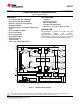
PCM3070 SLAS724 – FEBRUARY 2011 www.ti.com Typical Circuit Configuration MSP430 SCL IN1_L 7.5KW 2.49KW SDA MCLK 0.47mF BCLK DIR9001 2.49KW WCLK IN1_R 0.47mF 7.5KW DIN 7.5KW 2.49KW 0.47mF IN2_L TAS57xx 2.49KW DOUT IN2_R PCM3070 0.47mF 7.5KW 100W LOL 1mF 1KW 0.047mF 7.5KW 2.49KW 0.47mF IN3_L 0.047mF 0.47mF IN3_R 100W HPL LDOIN IOVDD REF DVDD AVDD IOVSS DVSS AVSS LDO_SELECT 2.49KW 7.
PCM3070 SLAS724 – FEBRUARY 2011 www.ti.com Multifunction Pins Table 8 shows the possible allocation of pins for specific functions. The PLL input, for example, can be programmed to be any of 4 pins (MCLK, BCLK, DIN, GPIO). Table 8.
PCM3070 SLAS724 – FEBRUARY 2011 • • www.ti.com Fast charge of ac-coupling capacitors Anti thump Analog Bypass The PCM3070 offers two analog-bypass modes. In either of the modes, an analog input signal can be routed from an analog input pin to an amplifier driving an analog output pin. Neither the ADC nor the DAC resources are required for such operation.
PCM3070 SLAS724 – FEBRUARY 2011 www.ti.com • • • • • • • 2 programmable gain amplifiers (PGA) with a range of 0 to +47.5dB 2 mixer amplifiers for analog bypass 2 analog bypass channels Fine gain adjust of digital channels with 0.
PCM3070 SLAS724 – FEBRUARY 2011 www.ti.com Table 9.
PCM3070 SLAS724 – FEBRUARY 2011 www.ti.com DAC The PCM3070 includes a stereo audio DAC supporting data rates from 8kHz to 192kHz. Each channel of the stereo audio DAC consists of a signal-processing engine with fixed processing blocks, a programmable miniDSP, a digital interpolation filter, multi-bit digital delta-sigma modulator, and an analog reconstruction filter.
PCM3070 SLAS724 – FEBRUARY 2011 www.ti.com Table 10. Overview – DAC Predefined Processing Blocks (continued) Processing Block No. Interpolation Filter Channel 1st Order IIR Available Num.
PCM3070 SLAS724 – FEBRUARY 2011 www.ti.com The PCM3070 further includes programmability (Page 0, Register 27, D0) to place the DOUT line into a hi-Z (3-state) condition during all bit clocks when valid data is not being sent. By combining this capability with the ability to program at what bit clock in a frame the audio data begins, time-division multiplexing (TDM) can be accomplished, enabling the use of multiple codecs on a single audio serial data bus.
PCM3070 SLAS724 – FEBRUARY 2011 www.ti.com For more detailed information see the PCM3070 Application Reference Guide, SLAU332. Device Special Functions The following special functions are available to support advanced system requirements: • Interrupt generation • Flexible pin multiplexing For more detailed information see the PCM3070 Application Reference Guide, SLAU332. MiniDSP The PCM3070 features two miniDSP cores.
PCM3070 SLAS724 – FEBRUARY 2011 www.ti.com Table 11. Summary of Register Map (continued) Decimal Hex DESCRIPTION PAGE NO. REG. NO. PAGE NO. REG. NO.
PCM3070 SLAS724 – FEBRUARY 2011 www.ti.com Table 11. Summary of Register Map (continued) Decimal Hex DESCRIPTION PAGE NO. REG. NO. PAGE NO. REG. NO.
PCM3070 SLAS724 – FEBRUARY 2011 www.ti.com Table 11. Summary of Register Map (continued) Decimal Hex DESCRIPTION PAGE NO. REG. NO. PAGE NO. REG. NO.
PCM3070 SLAS724 – FEBRUARY 2011 www.ti.com Table 11. Summary of Register Map (continued) Decimal Hex DESCRIPTION PAGE NO. REG. NO. PAGE NO. REG. NO. 44 2-7 0x2C 0x02-0x07 Reserved 44 8-127 0x2C 0x08-0x7F DAC Coefficients Buffer-A C(0:29) 45-52 0 0x2D-0x34 0x00 Page Select Register 45-52 1-7 0x2D-0x34 0x01-0x07 Reserved.
PACKAGE OPTION ADDENDUM www.ti.
PACKAGE MATERIALS INFORMATION www.ti.com 27-Jul-2013 TAPE AND REEL INFORMATION *All dimensions are nominal Device Package Package Pins Type Drawing SPQ Reel Reel A0 Diameter Width (mm) (mm) W1 (mm) B0 (mm) K0 (mm) P1 (mm) W Pin1 (mm) Quadrant PCM3070IRHBR VQFN RHB 32 3000 330.0 12.4 5.3 5.3 1.5 8.0 12.0 Q2 PCM3070IRHBT VQFN RHB 32 250 180.0 12.4 5.3 5.3 1.5 8.0 12.
PACKAGE MATERIALS INFORMATION www.ti.com 27-Jul-2013 *All dimensions are nominal Device Package Type Package Drawing Pins SPQ Length (mm) Width (mm) Height (mm) PCM3070IRHBR VQFN RHB 32 3000 367.0 367.0 35.0 PCM3070IRHBT VQFN RHB 32 250 210.0 185.0 35.
IMPORTANT NOTICE Texas Instruments Incorporated and its subsidiaries (TI) reserve the right to make corrections, enhancements, improvements and other changes to its semiconductor products and services per JESD46, latest issue, and to discontinue any product or service per JESD48, latest issue. Buyers should obtain the latest relevant information before placing orders and should verify that such information is current and complete.