
Datasheet

www.ti.com
PGA870EVM Control Panel Graphical User Interface (GUI)
3 PGA870EVM Control Panel Graphical User Interface (GUI)
The gain of the device on the EVM may be controlled from a computer by using the PGA870 control panel
GUI, the USB interface board in the EVM kit, and a USB cable. The GUI software installer (discussed in
Section 4) is on the CD shipped with the EVM kit, and is also available for download through the PGA870
product folder on the TI web site. The GUI controls only the bits B0 to B5 of the gain control word. The
control panel GUI does not control the Gain Strobe or Latch Mode control lines of the PGA870 itself.
When using the GUI software, the Gain Strobe and Latch Mode lines must be controlled with the EVM
onboard switches (S1 and S3) or with external connections.
4 GUI Software Installation and Use
To install the PGA870EVM GUI software, copy the software installer and the folder USB_drivers from the
enclosed CD onto the Microsoft
®
Windows
®
desktop of the target computer. Double-click on the installer
icon and follow the instructions to begin the installation; accept the terms of use and licensing agreements
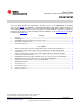
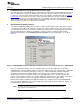
when that prompt appears. When the installation is complete, start the control panel GUI from the
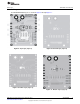
Windows Start menu by selecting PGA870_Control_Panel.exe. The GUI should appear, as shown in
Figure 4.
Figure 4. PGA870EVM Control Panel GUI After Installation, Before Successful Connection to PGA870EVM
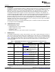
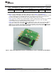
Once the control panel GUI has been successfully installed, connect the USB interface board to the
PGA870EVM J8 connector (DB25), and then connect the USB port to the host computer with a USB cable
(provided). After connecting the USB cable, you may see a Microsoft Windows notification that New
hardware has been found, and that new drivers are required. If you receive this notification, use the
Browse option to direct the hardware installer to find the USB_Drivers folder. The driver installer may
require several iterations in order to successfully complete the update process. The number of new drivers
that are required depends on the host computer configuration and its unique update history.
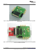
After the GUI software installation and USB driver updates are completed, power up the PGA870EVM;
make sure that the PGA870 device is in the Enabled state with switch S2, and the gain latch mode is set
to Unlatched with switches S1 and S3.
NOTE: The EVM connection and switch (S3) labeled CLOCK provides the Gain Strobe function
discussed in the product data sheet.
5
SBOU082A–December 2009–Revised February 2010 PGA870EVM
Submit Documentation Feedback
Copyright © 2009–2010, Texas Instruments Incorporated