
Datasheet

GUI Software Installation and Use
www.ti.com
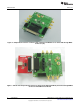
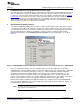
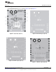
Once the connections are configured, click on the Connect button on the upper left corner of the control
panel GUI. If the control panel successfully connects to the PGA870EVM, then the button label changes
from Connect to Disconnect as Figure 5 shows. If the control panel software cannot connect to the
PGA870EVM, the Connect button does not change to Disconnect. No other error message is generated.
Note: The button has changed from Connect to Disconnect.
Figure 5. PGA870EVM Control Panel GUI After Successful Connection to PGA870EVM
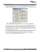
The boxes on the left side of the control panel GUI (see Figure 4) under the GainBit heading indicate the
corresponding gain control bits as described in the PGA870 product data sheet. Bit B0 is the least
significant bit (LSB) of the gain control word; it represents the smallest gain step of 0.5 dB. Bit B5 is the
largest gain step (16 dB), and corresponds to the most significant gain control bit (MSB). Checking a box
causes the GUI software to send a high signal to the corresponding gain control bit. Figure 5 corresponds
to a minimum PGA870 gain of –11.5 dB.
The PGA870 gain corresponding to the gain setting (that is, the GainBit checked boxes) appears in the
number field entitled, Overall PGA870 Gain (dB). The actual measured gain of the EVM may be less than
the selected PGA870 gain because of losses in the resistive load and the EVM transformers.
The number field labeled Input Attenuation (dB) shows the equivalent loss of the PGA870 input
attenuator. Consult the device data sheet for additional information.
6
PGA870EVM SBOU082A–December 2009–Revised February 2010
Submit Documentation Feedback
Copyright © 2009–2010, Texas Instruments Incorporated