
User manual

SLUU186 − March 2004
9
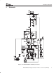
TPS40055-Based Design Converts 12-V Bus to 1.8 V at 15 A (HPA070)
4.8 Short Circuit Protection
The TPS40055 implements short circuit protection by comparing the voltage across the topside MOSFET while
it is ON to a voltage developed across R
LIM
due to an internal current source of 10 µA inside pin 16. Both of these
voltages are negative with respect to V
IN
. From the datasheet equation, R
LIM
is defined as:
R
LIM
+ R9 +
I
OC
R
DS(on) (max)
1.12 I
SINK
+
V
OS
I
SINK
+ (W)
where
• I
OC
is the overcurrent set point equal to the DC output current plus one-half the inductor ripple current
• V
OS
is the overcurrent comparator offset, and Isink is the current into ILIM (pin 16).
Using worst case tolerances the value of R
LIM
should be maximized to ensure that the converter can deliver full
rated current under all conditions. In a worst case condition, R
LIM
=R9 and
R
LIM
+
(
15 A ) 1.5 A
)
(
7.9 mW 1.45
)
1.12 8.65 mA
)
* 30 mV
8.65 mA
+ 16.0 kW
The standard value of 16.2 kΩ was selected. This ensures that we can deliver a minimum of 15 A before current
limit is activated. There is also a small capacitor, C7, placed in parallel with R9 to filter the signal.
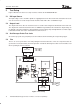
4.9 Snubber Component Selection
Initially, the junction of Q1, Q2, and L1 was ringing at a frequency near 100 MHz with a peak voltage near 30
V. This was due to the extremely fast switching speed of the MOSFETs and the lack of any cross−conduction.
C13 was added to shunt the high-frequency ringing to ground and the peak voltage is now below 25 V.
4.10 Compensation Components
The TPS40055 uses voltage mode control with feed-forward in conjunction with a high-frequency error amplifier
to implement closed loop control. The power circuit L-C double pole corner frequency f
C
occurs at 3.8 kHz, and
the output capacitor ESR zero is located at approximately 38 kHz. The feedback compensation network is
implemented to provide two zeroes and three poles. The first pole is placed at the origin to improve DC
regulation.
The first zero is placed at 2.8 kHz, just below the L-C corner frequency.
f
Z1
+
1
2p R5 C5
The second zero is selected to be coincident with the L-C corner frequency of 3.8 kHz,
f
Z2
+
1
2p
(
R7 ) R8
)
C6
The second pole is placed near the ESR zero frequency at 37 kHz.
f
P1
+
1
2p R5
ǒ
C4 C5
C4)C5
Ǔ
and the third pole is placed at 150 kHz, which is one-half the switching frequency.
f
P2
+
1
2p R8 C6
(10)
(11)
(12)
(13)
(14)
(15)