
Datasheet


Table Of Contents
- FEATURES
- APPLICATIONS
- DESCRIPTION
- ENVIRONMENTAL AND ABSOLUTE MAXIMUM RATINGS
- ELECTRICAL CHARACTERISTICS
- ELECTRICAL CHARACTERISTICS
- TYPICAL CHARACTERISTICSThe electrical characteristic data has been developed from actual products tested at 25C. This data is considered typical for the converter. Applies to , , and .The temperature derating curves represent the conditions at which internal components are at or below the manufacturer's maximum operating temperatures. Derating limits apply to modules soldered directly to a 100 mm x 100 mm double-sided PCB with 2 oz. copper. For surface mount packages (AS and AZ suffix), multiple vias must be utilized. Please refer to the mechanical specification for more information. Applies to .
- TYPICAL CHARACTERISTICSThe electrical characteristic data has been developed from actual products tested at 25C. This data is considered typical for the converter. Applies to , , and .The temperature derating curves represent the conditions at which internal components are at or below the manufacturer's maximum operating temperatures. Derating limits apply to modules soldered directly to a 100 mm x 100 mm double-sided PCB with 2 oz. copper. For surface mount packages (AS and AZ suffix), multiple vias must be utilized. Please refer to the mechanical specification for more information. Applies to .
- APPLICATION INFORMATION
- ADJUSTING THE OUTPUT VOLTAGE
- CAPACITOR RECOMMENDATIONS FOR THE PTH04T240/241W POWER MODULE
- TurboTrans Technology
- TurboTrans Selection
- UNDERVOLTAGE LOCKOUT (UVLO)
- Soft-Start Power Up
- On/Off Inhibit
- Smart Sync
- Overcurrent Protection
- Overtemperature Protection (OTP)
- Differential Output Voltage Remote Sense
- Auto-Track Function
- Tape & Reel and Tray Drawings
1
FEATURES
APPLICATIONS
DESCRIPTION
PTH04T240W , PTH04T241W
www.ti.com
...................................................................................................................................................... SLTS276D – OCTOBER 2006 – REVISED JULY 2009
10-A, 2.2-V to 5.5-V INPUT, NON-ISOLATED,
WIDE-OUTPUT, ADJUSTABLE POWER MODULE WITH TURBOTRANS™
2
• Up to 10-A Output Current
• Complex Multi-Voltage Systems
• 2.2-V to 5.5-V Input Voltage
• Microprocessors
• Wide-Output Voltage Adjust (0.69 V to 3.6 V)
• Bus Drivers
• ± 1.5% Total Output Voltage Variation
• Efficiencies up to 96%
• Output Overcurrent Protection
(Nonlatching, Auto-Reset)
• Operating Temperature: – 40 ° C to 85 ° C
• Safety Agency Approvals:
– UL/IEC/CSA-C22.2 60950-1
• Prebias Startup
• On/Off Inhibit
• Differential Output Voltage Remote Sense
• Adjustable Undervoltage Lockout
• Auto-Track™ Sequencing
• Ceramic Capacitor Version (PTH04T241W)
• TurboTrans™ Technology
• Designed to meet Ultra-Fast Transient
Requirements up to 300 A/ µ s
• SmartSync Technology
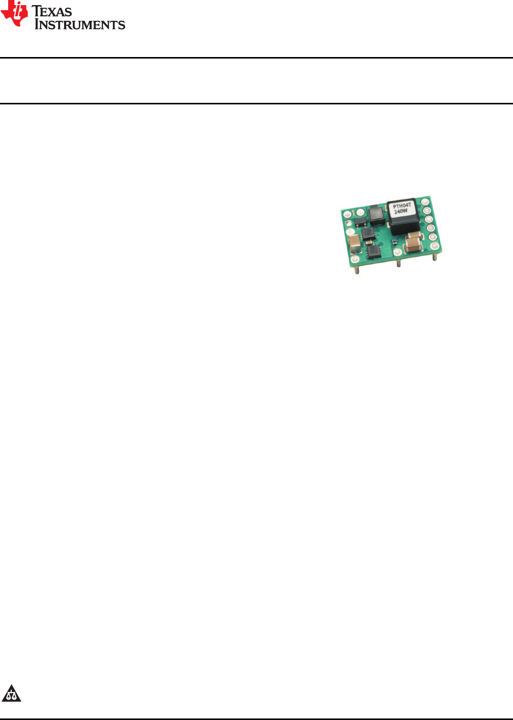
The PTH04T240/241W is a high-performance 10-A rated, non-isolated power module. These modules represent
the 2nd generation of the popular PTH series power modules and include a reduced footprint and additional
features. The PTH04T241W is optimized to be used with all ceramic capacitors.
Operating from an input voltage range of 2.2 V to 5.5 V, the PTH04T240/241W requires a single resistor to set
the output voltage to any value over the range, 0.69 V to 3.6 V. The wide input voltage range makes the
PTH04T240/241W particularly suitable for advanced computing and server applications that utilize a 2.5-V,
3.3-V, or 5-V intermediate bus architecture.
The module incorporates a comprehensive list of features. Output over-current and over-temperature shutdown
protects against most load faults. A differential remote sense ensures tight load regulation. An adjustable
under-voltage lockout allows the turn-on voltage threshold to be customized. Auto-Track™sequencing is a
popular feature that greatly simplifies the simultaneous power-up and power-down of multiple modules in a
power system.
1
Please be aware that an important notice concerning availability, standard warranty, and use in critical applications of Texas
Instruments semiconductor products and disclaimers thereto appears at the end of this data sheet.
2 Auto-Track, TurboTrans, TMS320 are trademarks of Texas Instruments.
PRODUCTION DATA information is current as of publication date.
Copyright © 2006 – 2009, Texas Instruments Incorporated
Products conform to specifications per the terms of the Texas
Instruments standard warranty. Production processing does not
necessarily include testing of all parameters.